• Hello there guest and Welcome to The #1 Classic Mustang forum!
    To gain full access you must Register. Registration is free and it takes only a few moments to complete.
    Already a member? Login here then!

69/70 Instrument Cluster Removal

RagTop

Old Grumpy
I'm still screwing around with replacing the dash light bulbs and voltage regulator on my 69 vert while I've got the dash pad off the car. I just tried to pull the cluster forward and I realized that the wiring and the speedo cable seem to have it pinned. It moves forward less than 1" before reaching the extent of the slack in the connections. The official Ford shop manual says to disconnect the plug from the harness to the PC board and to disconnect the speedo cable by depressing the tab on the side of the connector and thence remove the cluster. Well, I can't get the cluster far enough forward to fit my meat hooks behind it to pull said connections. Also, I'm guessing that the factory plug to the PC board is a locking type that requires the depression of some sort of detent clip to separate it. Does anyone here have any apriori knowledge of removing this thing? I find that a little course knowledge serves better than a ream of vague manuals. Help!
 
There is a retaining clip on each end of the dash cluster connector, and you have to press it inwards while pulling the connector back. I've found wrapping my left arm around the right side of the dash cluster to be fairly effective...think of a policeman twisting your arm behind your back.
 
Well, I just came back from the garage and, by some unknown technique, the stupid plug finally disconnected. I was told in the 69 Ford Manual that this should provide access to the speedometer cable. WRONG! Unless you have Go-Go-Gadget arms you aren't going to get to the speedo cable. Releasing the harness does NOT provide any more slack to get the cluster further out of the dash and there isn't enough clearance to reach the speedo cable from either side. If it isn't obvious, I am beginning to lose my patience with this whole project. Who would design a car so that you have to remove the whole frickin dash to change light bulbs? Of course, anyone who has ever changed a heater core on a Ford will understand who those guys are. Again, help from anyone who's done a 69/70 cluster removal would be deeply appreciated.

TIA

BTW, I do have the dash pad off the car. That's why I thought it would be a great chance to change those dim/burnt out light bulbs.
 
On a 68, there's a clip on the engine side of the firewall holding the cable down. Releasing the cable from that clip will allow you to pull the cluster out further.
 
I removed the trim piece below my steering column, which allowed the instrument cluster to move slightly further forward. Still can't reach the damn thing from either side. The speedometer cable is the restricting issue. Is it possible (easier) to reach the speedo cable from below the dash? I'm beginning to lose hope that I'll ever get this thing out of the car. Besides, the printed circuit is printed on a light grade of translucent green plastic and I'm hitting the ends every time I try to reach for the speedo cable. I'm guessing that it is probably just as given to brittleness and age damage as the rest of the car's electricals and that I'm asking for major trouble by flexing it. Why in the hell did Ford design this so stupidly? I just want to change bulbs and the lousy voltage regulator! :rant
 
"RagTop" said:
I removed the trim piece below my steering column, which allowed the instrument cluster to move slightly further forward. Still can't reach the damn thing from either side. The speedometer cable is the restricting issue. Is it possible (easier) to reach the speedo cable from below the dash? I'm beginning to lose hope that I'll ever get this thing out of the car. Besides, the printed circuit is printed on a light grade of translucent green plastic and I'm hitting the ends every time I try to reach for the speedo cable. I'm guessing that it is probably just as given to brittleness and age damage as the rest of the car's electricals and that I'm asking for major trouble by flexing it. Why in the hell did Ford design this so stupidly? I just want to change bulbs and the lousy voltage regulator! :rant

IIRC, I had to completely loosen the whole driver's side cluster from the lower dash to get the wiggle room to get to my speedo cable connector. Might want to use a towel or something to protect the bezel from damage while it's wallowing around semi-loose as you attempt to get the cable free.

Since you'll have it out anyway, I would definitely paint the inside of the instrument housings flat white and at least consider upgrading to LED's if you do any night driving. It made a fair bit of difference on mine:

IMG_0574_500x.jpg


A little off the factory color, but 100% easier to see at night!

I replaced my printed circuit while I had the cluster out too, just as insurance against having to go back in later.


edit:

After re-reading, it seems like you already have everything loose. Try going from underneath like Mid said.

http://1970mgr.org/_InstrumentCluster.htm
2. Reach up from the floorboards and behind the instrument cluster and carefully remove the speedometer cable. Just squeeze the round plastic clip at the flat part you feel and gently pull the cable away from the speedometer.

If that doesn't work, try conning someone with smaller hands into giving it a try! :)
 
I actually got the damn thing out yesterday! :bow I called a local Mustang shop and he suggested pushing any slack in the speedometer cable through the firewall, creating more room to get my hand back there. Bingo! I was able to easily reach around the cluster and disconnect the speedo cable. Next, I've got to come up with two more LED 194 bulbs. The dash takes twelve and I only bought ten from NPD. BTW, local suppliers, if they had them in stock, are charging $6.50 per bulb. NPD's price for the LED 194 is $.099. Hope these aren't going to be a problem in the future. Anyone have any experience with the LED bulbs from NPD?

Doug 69: Your dash looks great. Mine is so dim at night that it's hard to see the gauges. Now you have me wondering if I should replace the PC sheet as well. BTW, does your ammeter work or does it just point down like the ones on our two 69s?
 
18 to 22 cents a piece at Rock Auto... and about 2.50 shipping.

If you call a parts store, and ask for a 10 or 12 pack, the price for the entire package usually doesn't include that crazy markup...
 
"RagTop" said:
Anyone have any experience with the LED bulbs from NPD?

I got mine as a set from NPD, the "5x":
http://www.npdlink.com/store/products/l ... 908-1.html

I believe they were the same Hipo Parts kit as these:
http://www.hipoparts.com/1965-73-ford-m ... rsion-kit/

One bulb was defective (came apart) but NPD replaced it. No problems otherwise.


"RagTop" said:
Doug 69: Your dash looks great. Mine is so dim at night that it's hard to see the gauges.

I could barely see my gauges either before installing the LEDs. They say they work with the rheostat but not really, at least mine barely have any range. But even if they did, I like 'em cranked all the way up anyway.


"RagTop" said:
Now you have me wondering if I should replace the PC sheet as well.

Replacing the printed circuit was a must for me because mine was in bad shape. I don't want to talk you into spending money if you don't have to though.


"RagTop" said:
BTW, does your ammeter work or does it just point down like the ones on our two 69s?

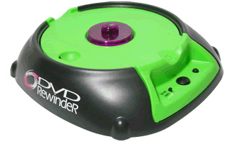
Either my charging system is rock steady or my ammeter is about as useful as one of these:

dvdrewinder.jpg
 
We should take a poll on those 69-70 ammeters. Both of ours just seem to be the victims of gravity, hanging straight down and never budging. Doesn't matter what's going on with the car's electricals, they just sit there pointing to the floorboard. What a joke. BTW, are ammeters different than voltage gauges? In my other cars I have voltage gauges and they respond to anything from turning on the headlights to engaging the turn signals. They also go to a charge status after a startup. Sort of useful, but they don't show me my amperage (whatever the hell that is).
 
Amperage measures the amount of current flow; volt-meters measures volts. The relationship between volts (V) and current (i) is: I*R = V where R is resistance.
 
"Midlife" said:
Amperage measures the amount of current flow; volt-meters measures volts. The relationship between volts (V) and current (i) is: I*R = V where R is resistance.
So the ammeter tells me what the current flow is, irrespective of resistance, and the voltage meter tells me what the current flow is net of resistance? Hence, the voltage meter moves around when the resistance is increased by using the electrical systems while the ammeter remains constant (whether it's working or not)? Obviously electrical is a black art to me. Assuming that the ammeter in our Mustangs work, what are they telling me about the car? I can relate to the voltage meter telling me how many volts the car is charging at, but I really don't get what an ammeter is telling me except that there is constant current flow.
 
You can have voltage with no current flowing, but you can't have current without voltage.

One of the best analogs is water pressure (voltage), flow rate (current), and pipe size (resistance). If you can understand how hydraulics work, then you can work out electricity. So...you can have water pressure with no flow at a valve; as you open the valve (resistance going from very high to low) flow rate increases and water pressure pretty much stays the same, although it may drop just a tad.

I'll agree in general that a voltmeter is much more useful to the average motorist, but the ammeter is a direct measure of whether your charging system is working or not; a voltmeter cannot tell you that directly. You can only infer it my seeing that the voltage is less than normal when driving that something is amiss.
 
You notice that I didn't get into how electrons flow? In actuality, current flow is caused by holes moving from the negative battery terminal to the positive terminal and not electrons flowing from positive to negative.
 
So, I installed my instrument cluster yesterday and I decided to hook up the battery and test it out before I expended any more effort on reassembling the dash. Everything came up with a nice blue light except the stupid no-workie ammeter. Maybe it knew I said bad things about it on this forum. Anyway, there is no light to be seen in the left most bezel of my dash. The thing is pitch black. IIRC, there were three bulbs clustered around the ammeter, so I'm guessing it is something besides a bulb or the mounting of same on the circuit board. Since I'm an electrical nebbish, I am guessing that the problem must reside in either the contact between the harness plug and the printed circuit where it hooks up to the circuit going to the ammeter illumination, or in the printed circuit itself. I shudder to think that I might have screwed up the harness wiring when I was trying to disconnect the plug. Again, this is exactly what I should have expected by getting involved with the dash illumination, but I a ever the optimist. Any of you electrical gurus out there have any suggestions as to how to proceed from here?

I just went out in the garage and decided to check the instrument's operation and turn signals. The turn signals illuminate and operate. The instruments don't work. No temp reading, no gas reading, no oil pressure reading. I did replace my old instrument voltage regulator with one of the solid state units from NPD. Could this be the cause of the failure of these gauges to operate?
 
If one dash lamp works, the rest should as well, unless a bulb is out. If not, then the circuit board or the bulb housing is indicated to be bad.

No gauge function: was the key in ACC or RUN?

The ammeter lines connect directly with the starter solenoid and alternator. To test them, remove the dash cluster and briefly use a C or D cell battery against the posts. The ammeter has no relationship to the nearby bulbs.

There have been a spate of bad repro circuit boards for 69 and 70 recently. I had one customer go through 3 before he found one that worked.
 
I'll try replacing one bulb tomorrow and see if that works.

The engine was running when the gauges were laying dead. I replaced the 46 year old voltage regulator with a new solid state model. The new regulator was just an L shaped metal bracket with a cube of resin with two wires sticking out of it that connected to the PC board. The instructions recommended mounting it with the wires pointing down. If that was done the metal foot sat on top of the alignment tit on the back of the cluster, effectively causing the foot to not make contact with the copper pad where the old regulator sat. I mounted it 180* out with the wires pointing up and the foot sitting mostly on the copper pad. Maybe that was a mistake. I'll pull it and either re-orient it or replace it with the original part that was still functioning when I pulled it "because I was in there".

I really don't care if the ammeter works or not, as long as it illuminates when I turn the lights on. I been living without any information from the ammeter for the last 16 years and I believe I can soldier on.

I didn't replace the circuit board on the car, so it's the original piece that was working great before I "fixed" it. I know I flexed the upper corners when I was disconnecting and reconnecting the speedo and the harness. Maybe I broke something unintentionally.

Who needs this crap? Ford engineers should be summarily executed for their lousy maintainability designs.
 
Back
Top