Navigation
Install the app
How to install the app on iOS
Follow along with the video below to see how to install our site as a web app on your home screen.

Note: This feature currently requires accessing the site using the built-in Safari browser.
More options
-
Hello there guest and Welcome to The #1 Classic Mustang forum!
To gain full access you must Register. Registration is free and it takes only a few moments to complete.
Already a member? Login here then!
You are using an out of date browser. It may not display this or other websites correctly.
You should upgrade or use an alternative browser.
You should upgrade or use an alternative browser.
Explorer 8.8 build DIY COMPLETE!!!
- Thread starter 67FSTBKRestoMod
- Start date
67FSTBKRestoMod
Member
"fordrule" said:yes indeed, i just found a rear end for 100 bux..now i just got to find another short axle to be good..where did you find another short axle for that inexpensive?
Pick n pull formerly pull a part, took apart the rear and just took the short side axle out.
67FSTBKRestoMod
Member
Wanted to add how i tackled the little parking brake problem. I took the parking brake cables with the rear when i bought it so i cut the little fittings off the explorers cables, keep the springs they will be used and cut a slit down the center of it a little bit with a 3" cut off wheel.
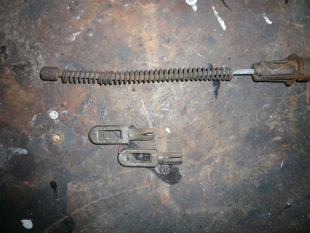
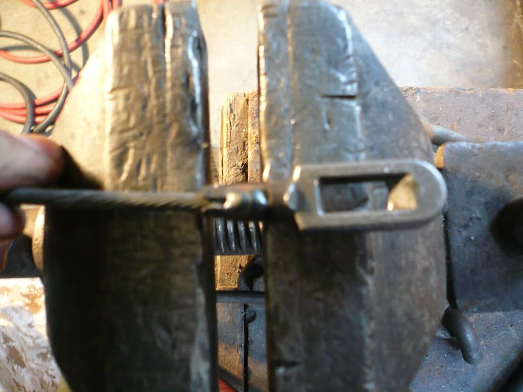
Cut off the old drum fittings from the stangs parking cable, Spring first then slip that puppy in that slit and weld part way up the slit DO NOT GO ALL THE WAY. welding the cable causes it to fatigue and break when twisted bent, really moved in anyway and the cable will start to split. Doing it half way insures the cable that is moved around will not split and break.
There ya have it
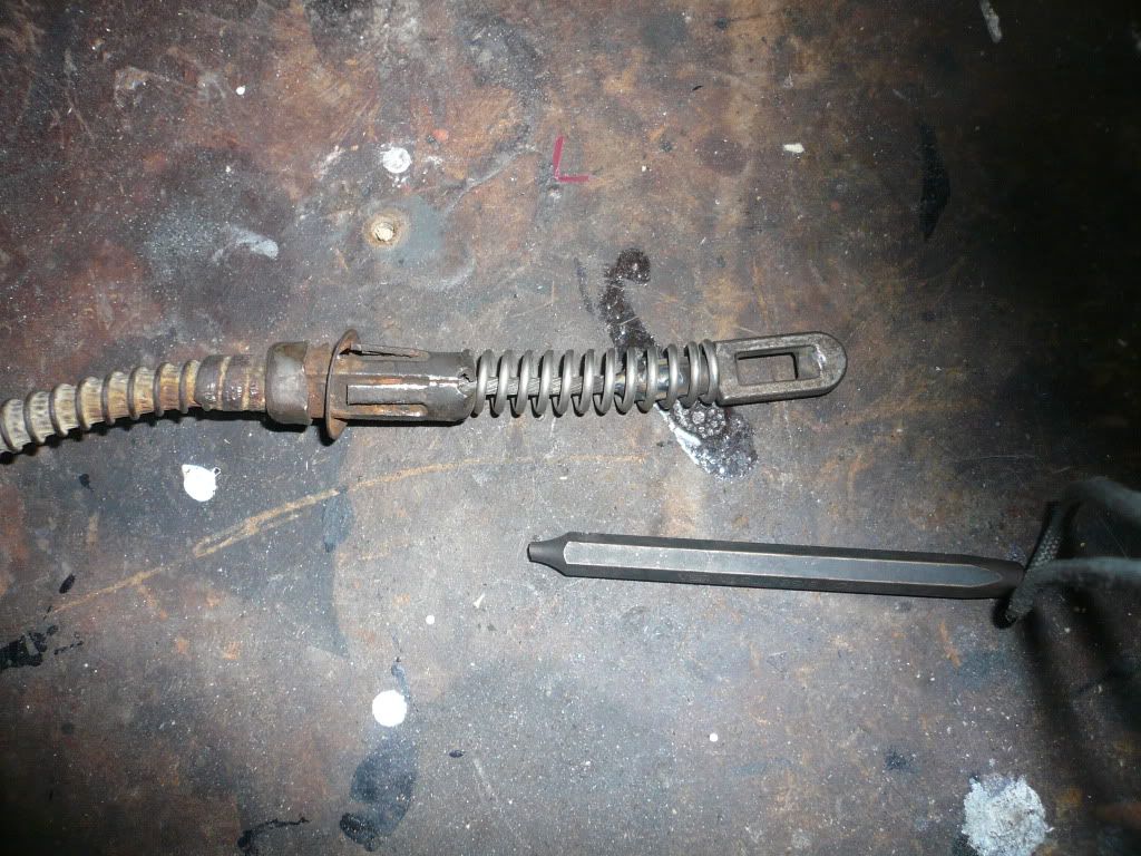
And for those that dont wanna spend the time i found these guys
http://www.speedwaymotors.com/E-Brake-Clevis-for-Ford-Explorer-and-Wilwood,37008.html
Cut off the old drum fittings from the stangs parking cable, Spring first then slip that puppy in that slit and weld part way up the slit DO NOT GO ALL THE WAY. welding the cable causes it to fatigue and break when twisted bent, really moved in anyway and the cable will start to split. Doing it half way insures the cable that is moved around will not split and break.
There ya have it
And for those that dont wanna spend the time i found these guys
http://www.speedwaymotors.com/E-Brake-Clevis-for-Ford-Explorer-and-Wilwood,37008.html
Last edited by a moderator:
Federico Garza
New Member
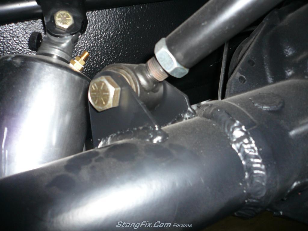
Nice work, mind sharing what you used to weld the tubes to the center section TIG/MIG or Arc???
67FSTBKRestoMod
Member
"Federico Garza" said:Nice work, mind sharing what you used to weld the tubes to the center section TIG/MIG or Arc???
Regular old MIG, I think TIG with some sort of nickel rod would have been the best way to go but IMO this is more than sufficient.
67FSTBKRestoMod
Member
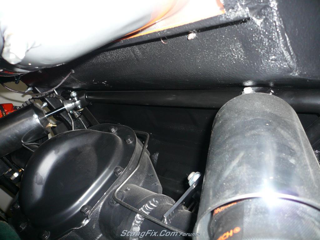
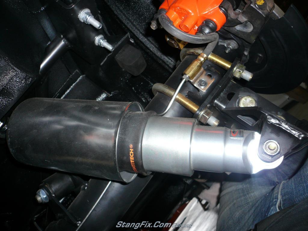
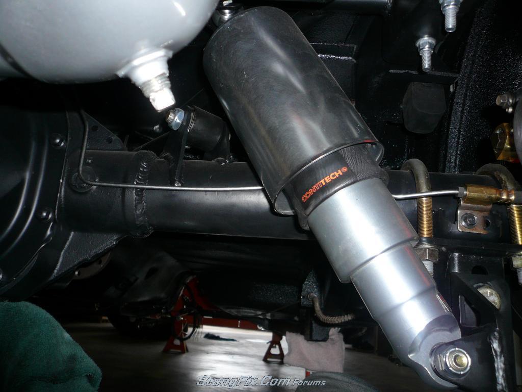
no, i wish i could say i fabbed that but some things aren't cost effective to make and this is one of em. its the airbar 2000 kit from ridtech, great kit decent price very easy install, i'll let you know how it handles when i get this puppy on the road.
http://www.ridetech.com/store/suspension-components/airbar/1964-1970-ford-mustang-airbar-system.html
http://www.ridetech.com/store/suspension-components/airbar/1964-1970-ford-mustang-airbar-system.html
67FSTBKRestoMod
Member
here ya r
Last edited by a moderator:
67FSTBKRestoMod
Member
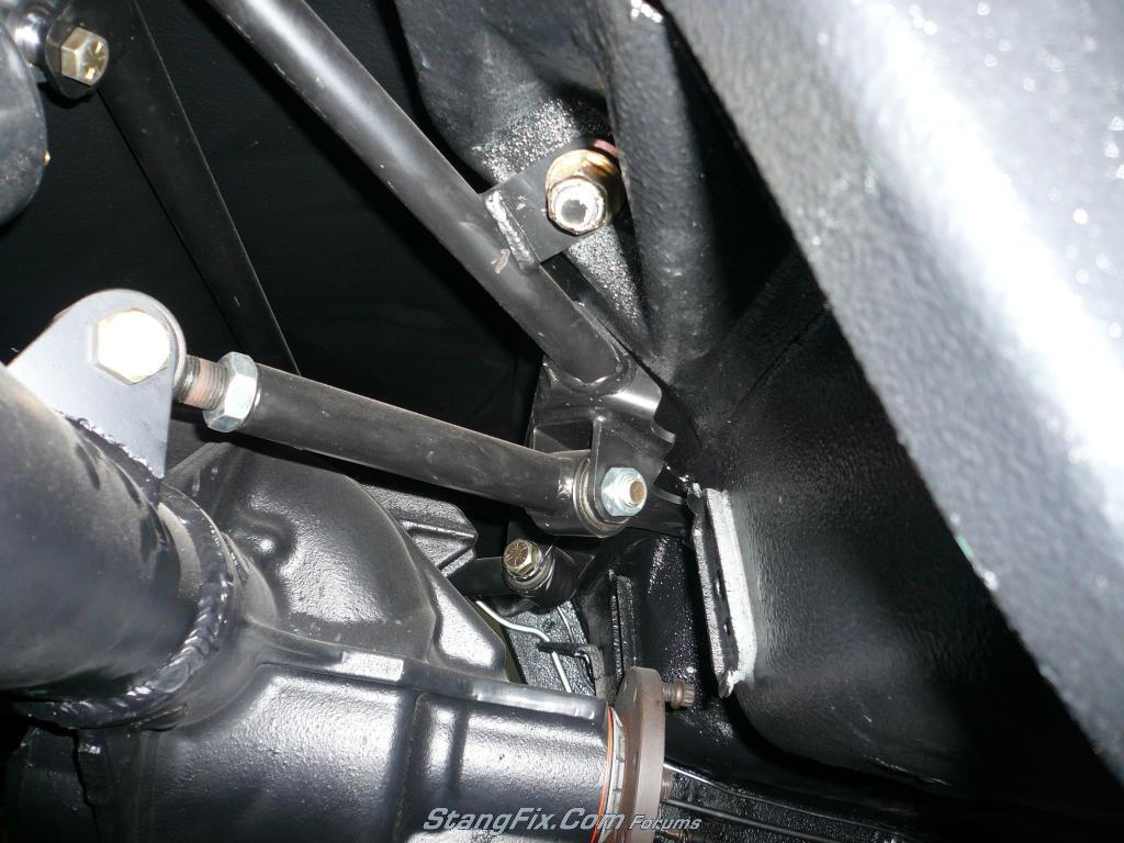
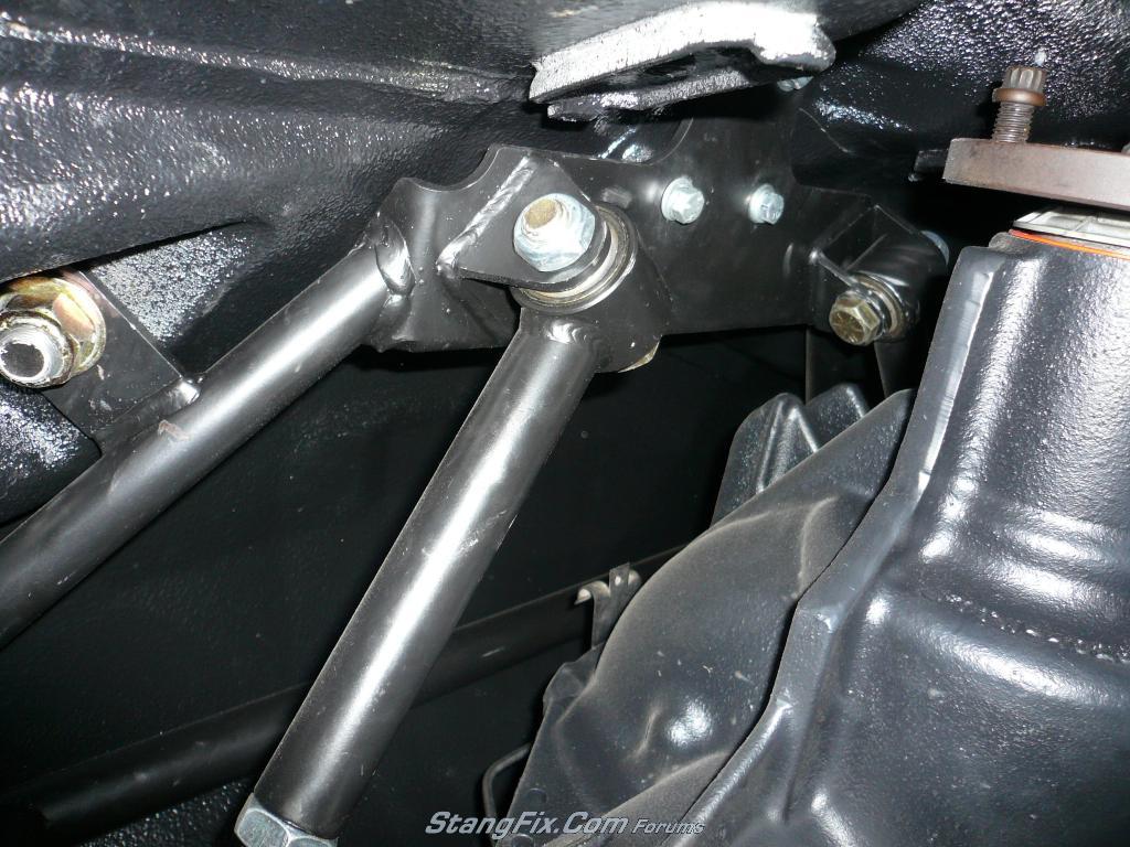
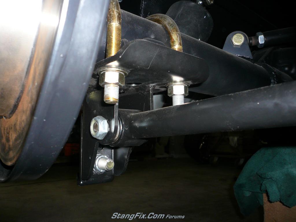
"ZFORCE" said:Thanks for the pics! I've been busy lately, so sorry for the late response. Was there a template for the upper mounts, to place them prior to welding the brackets? If not, how did you determine the angles?
not a prob, it actually took me some time to get them posted as well. No template, i basically installed everything (loose) centered the axle using plumbbobs and used a digital angle finder to set the pinion angle. normally i would have taken the angle off the tranny for 100% accuracy but no engine/tranny so i went with the general consensus that its about 3* pos... up whatever it is. (the 3* is from the rocker) the upper links are adjustable so you can fine tune the angel. once centered and angle correct i tack welded them in place, took her out welded completely up, painted and stuck back in.
hope that helps if not shot back.
Thanks, I guess I should've been more clear. I was wondering about templates for the upper link brackets that were welded to the axle tubes in your pictures, not the pinion angle. Since those upper brackets needed to be put on the axle in the correct spot and orientation, I was wondering how the kit guided you.
Wow, i must have missed this the first time around. Awesome build. Thanks for the pics too. It leaves me wondering though, if most people use spacers to use modern wheels, what wheels do you have planned for a rear end thats almost 3 inches shorter then stock? Am i correct in thinking that they would have to have a back spacing of 6 or 7 inchs? It doesnt look like you mini tubbed it or did you?
67FSTBKRestoMod
Member
zforce, the directions don't tell u much, i'm sure you can go to ur website and download the actual install instructions. i bolted everything up including the 2 upper links with the mounting tabs for the axle tubes bolted to the link itself. with angle set and everything lined up the mounting brackets sit on the axle tubes, tack welded them where they sat, pulled out and fully welded them.
lethal, the backspacing would depend on the wheel size, i went far from stock. got some foose injectors 18x9 with 4.25 backspacing(perfect fit)
if that doesn't help i'll keep trying
-brad
lethal, the backspacing would depend on the wheel size, i went far from stock. got some foose injectors 18x9 with 4.25 backspacing(perfect fit)
if that doesn't help i'll keep trying
-brad
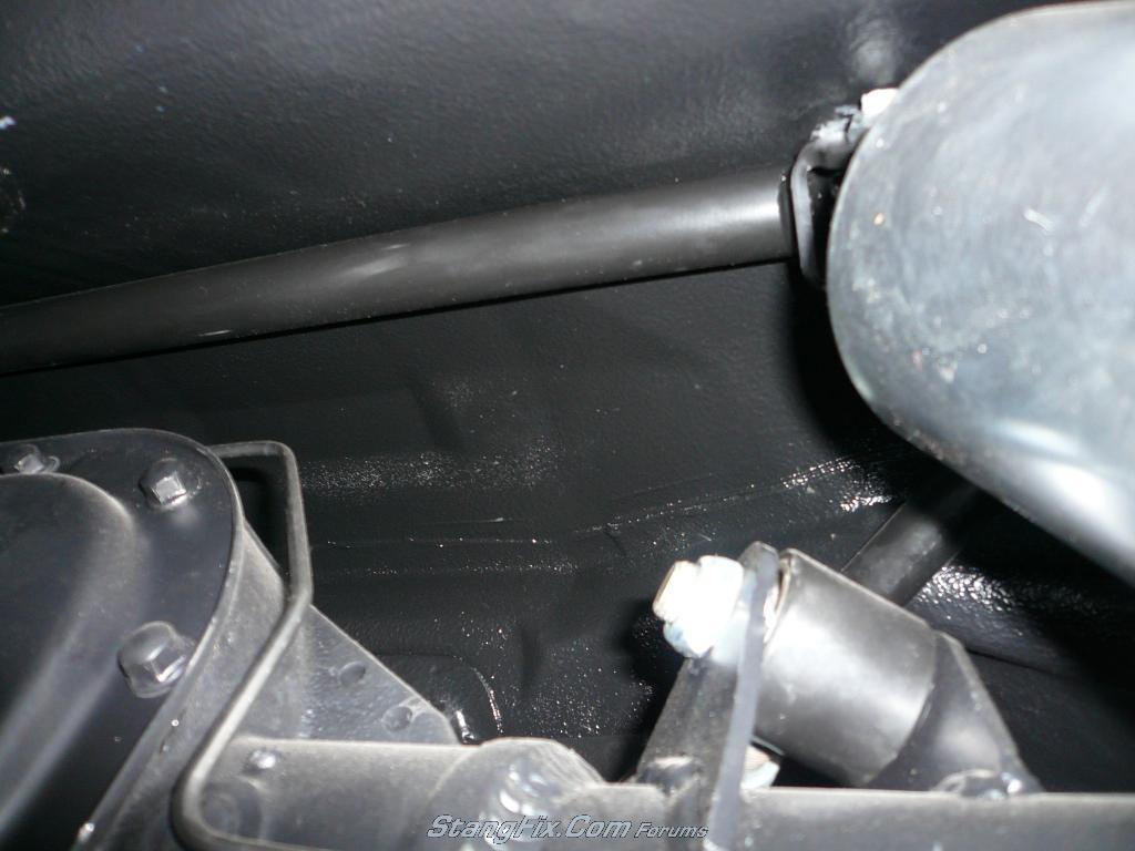
They fit. There are plenty of people who just relocate the perchs and bolt them in. supposedly, if you get an all aluminum drive shaft from a two wheel drive explorer that makes the transition to a C4 and is the perfect length. The thing that concerns me is the offset pinion angle. Plenty of people run them with the offset angle. Meaning the motor, transmission and drive shaft run down the center of the car. The explorer rear end is offset nearly 3 inchs to one side. It is possible with the added angle that you can get some drive line vibrations and possibly have problems with u joints. Again many people are doing it and reporting no problems.
The other issue is that with the offset housing, the pinion snout is no longer in the trans tunnel, so it may contact the floor board of you car before the bump stops contact the housing. This can be solved by hammering some clearance into the floor.
If you have duel exhaust, it may need to be adjusted in order to clear the offset housing as well.
Hope that helps.
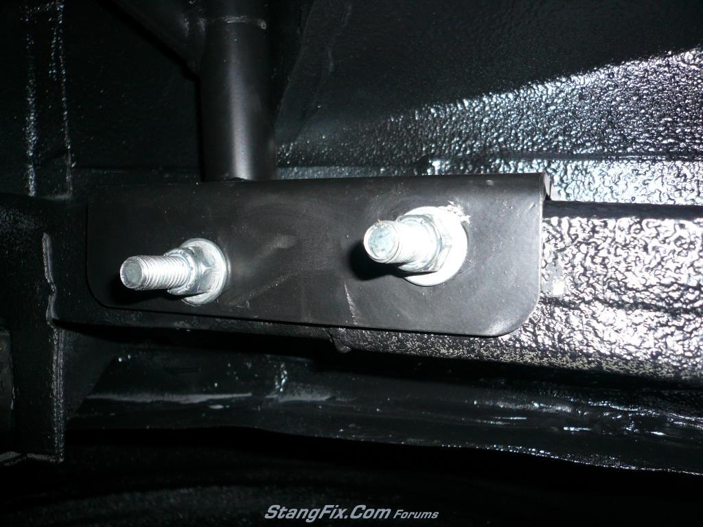
"67FSTBKRestoMod" said:to narrow it i first drilled out the plugs, starting with a smaller bit and working up to a 1/2 inch. I then used a chisel and hammer to smosh in the the head of the plug and pop it out. Then i used a 10 ton body ram to push the axle tube out, first marking the tube and diff housing for reference points for reinsert
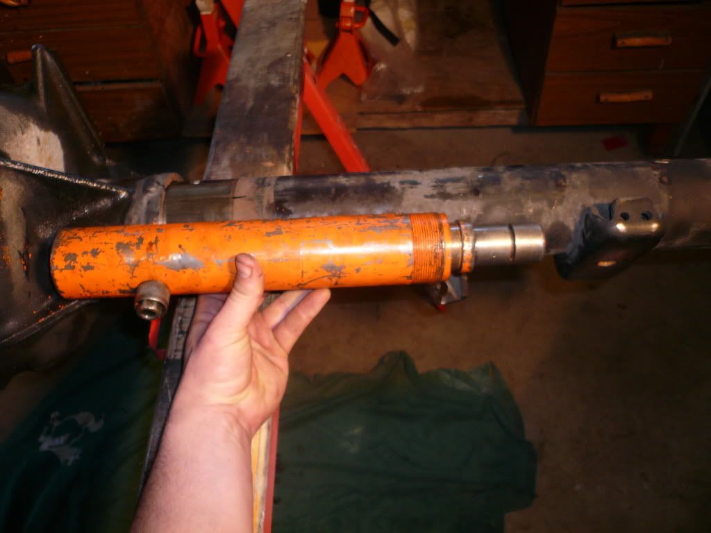
markings
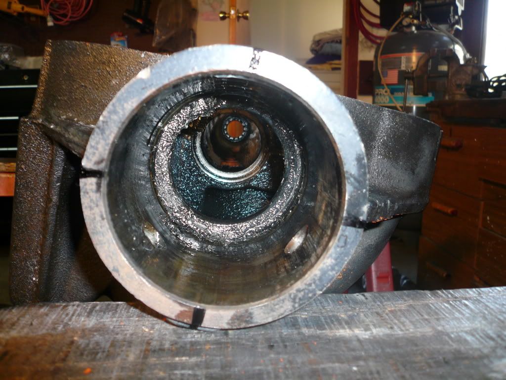
Can you elaborate on this part of your build a little bit please?
The ID of the axle tubes are larger in diameter than the casting where the shims/spacers go outside of the main bearings/caps (as shown in your second picture). The tubes are within 0.125" of being bottomed out on the casting (in out from centerline of the car), so I can't see anywhere to apply the ram of a cylinder to actually push the tube out from inside the gear housing.
Thanks for the whole posting and in advance for the additional help.
Jeff
Last edited by a moderator:
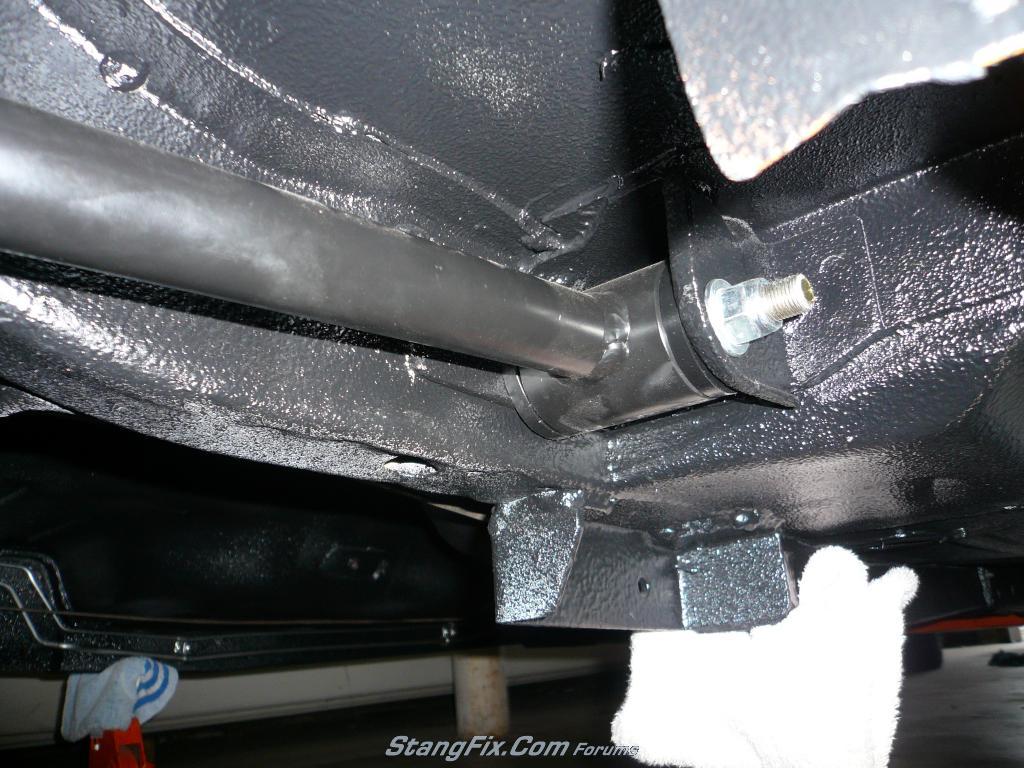
I don't *think* he pressed it out from the inside... My understanding / interpretation was that the ram was placed right where he has it shown. When pumped up, the left side sets on the center housing, and the ram pushed against the spring perch on the right side. I wouldn't image it would take much force given the plug welds are removed.
"stangg" said:...pushed against the spring perch on the right side.
Stangg,
Thanks. Make sense. Guess what I just finished cutting off of my housing... Maybe I can use an extension bar and get all the way out to the bracket that the brake plate mounts to.