• Hello there guest and Welcome to The #1 Classic Mustang forum!
    To gain full access you must Register. Registration is free and it takes only a few moments to complete.
    Already a member? Login here then!

My Custom Motor Mount build thread

buening

Active Member
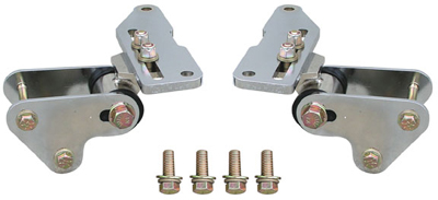
I've always like the Ron Morris motor mounts and everyone else seems to as well, but I just didn't want to fork out $225 for about $20 in steel and $20 in bushings. I also am not a fan of the urethane bushings used, so my design will utilize stock rubber bushings made for the rear shackles of our cars. If I find that the rubber wears too quickly or the bolt pushed through the rubber, I can always buy the urethane shackle bushings to replace these rubber ones.

Initially I wanted to mimic the Ron Morris design but I wasn't a fan of the motor mounts being of 3 sections: the top plate, the intermediate section consisting of a top plate/angled plate/bushing housing, and the shock tower brackets. I wanted to combine the top plate and bushing housing into one, similar to the TCP mounts but I didn't want to lose the option of sliding the engine back (which is the reason for these mounts). I decided to try to make the top plate have long slotted holes and make the front to back motor adjustments though those two bolts that go into the engine. The oil filter is in the way up front on the drivers side and there is a plug in the way on the front passenger side. Because of this, I conceded to try and mimic the Ron Morris mounts. RyanG85 and 65Fast helped with a getting me some measurements of their RM mounts, just for sanity checks to make sure I'm not way out of whack. Thanks guys!

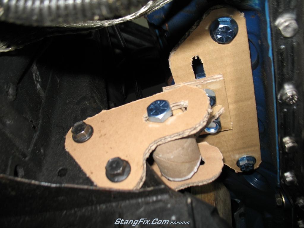
Here is what I have to take measurements from:

231_07_04_10_8_05_28.JPG


231_07_04_10_8_05_05.JPG


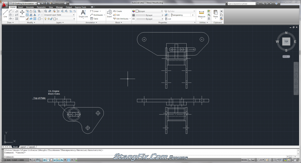
I used a caliper to take the measurements and below is what I came up with, drawn in Autocad:

231_07_04_10_7_49_22.png


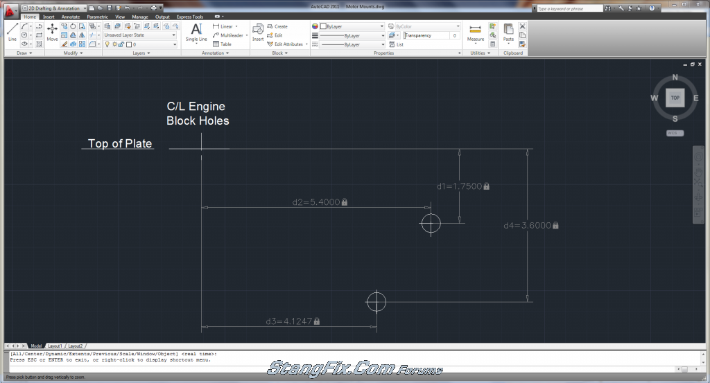
Using these dimensions, I drew up the shock tower brackets. I used 1/2" edge distance from the edge of bolt hole to edge of plate for 7/16" bolt holes (two for shock tower) and 5/8" edge distance for 1/2" bolt holes. I wanted to keep the cutting easy, so the top edge is flat. Due to the different edge distances from the two different bolt hole sizes, the hole centerlines are not inline as seen below:

231_07_04_10_7_49_57.png


The above drawing started out with pointed and square corners, and then I started drawing up circles that would be trimmed to make the rounded edges. Below is the result:

231_07_04_10_7_53_54.png


I also put in the bushing carrier and started to draw up the top plate. Below is next steps completed:

231_07_04_10_7_54_50.png


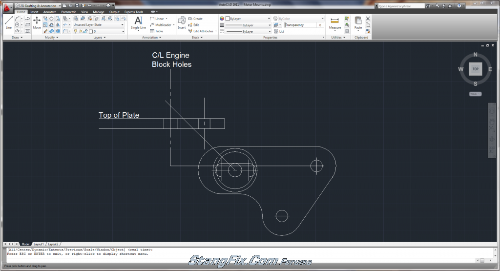
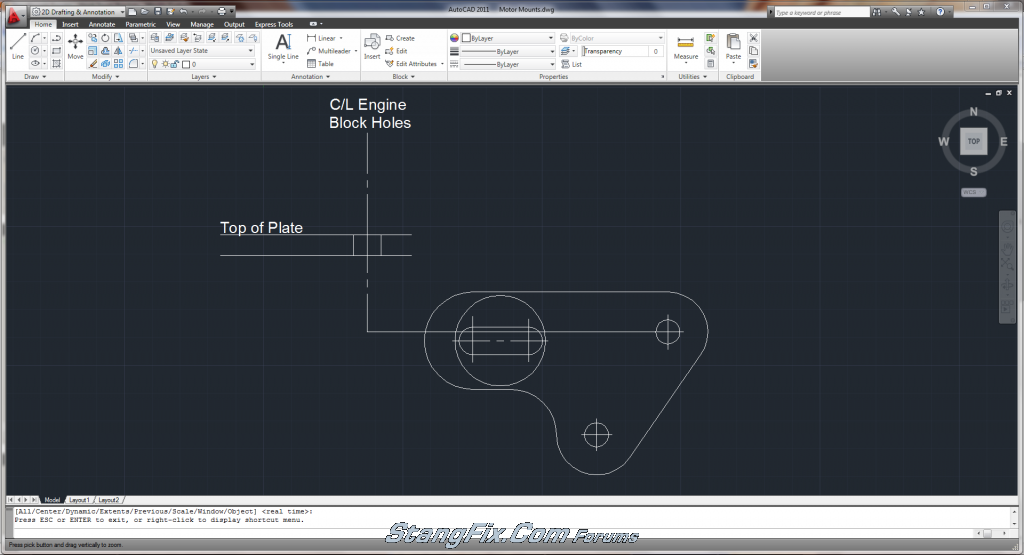
I established the bolt hole locations for the intermediate plate. The long line going at an angle is 45° from the centerline of the bushing. Its just a reference point so that the angle of the plate welded to the bushing housing doesn't get greater than that angle. The next step was finalizing the intermediate plate as seen below:

231_07_04_10_7_55_49.png


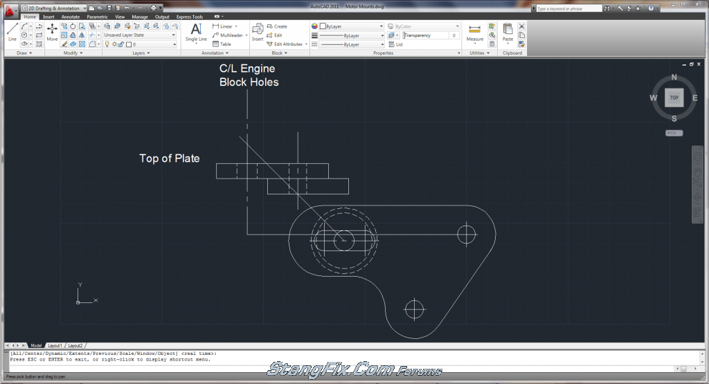
The final step was to draw in the angled plate that connects the bushing housing to the intermediate top plate.

231_07_04_10_7_57_53.png


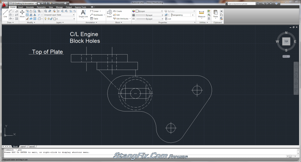
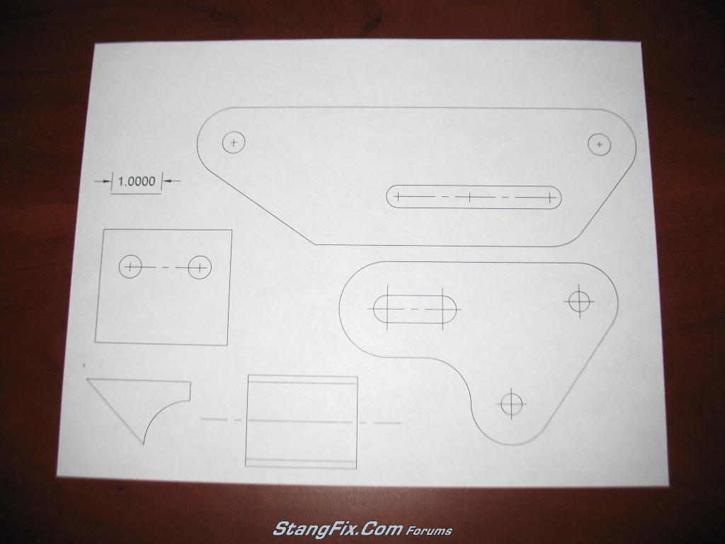
The above view is the completed side view of the motor mount assembly. This weekend I plan on drawing up the top view showing the width of the bushing, bushing housing, and details of the top plate and intermediate plate. I'm waiting on my rubber shackle bushings to come in the mail. When finalized, I will break up each part so that they can be transferred to steel plate to be cut. I plan on dimensioning everything and posting it on here so that other DIY guys can mimic my mounts...at your own risk of course :scar More to come later!

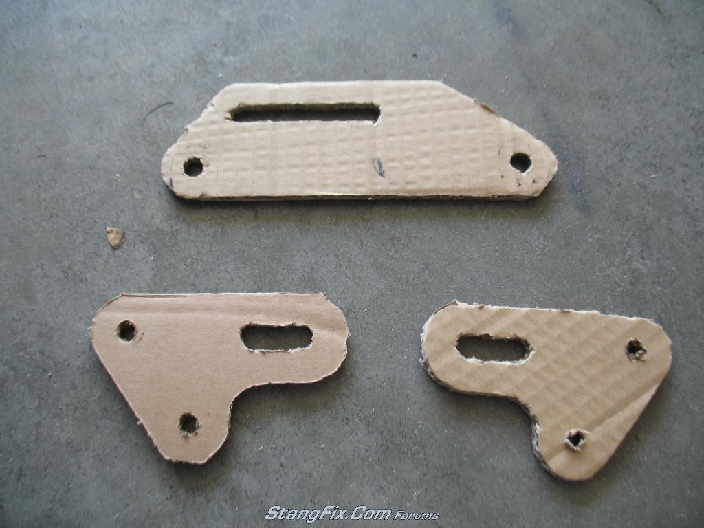
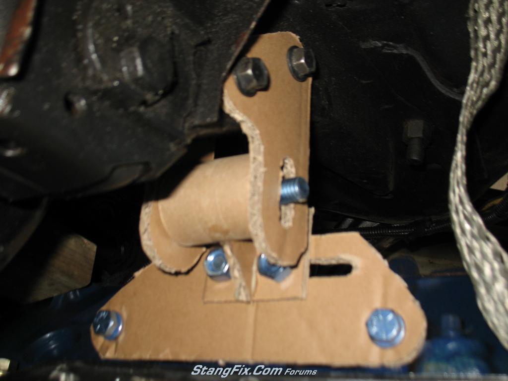
Oh, forgot to mention that when finished I'll be transferring these drawings onto cardboard for mock-up rather than going straight to cutting steel. Just in case something is off! :lol
 
Last edited by a moderator:
It's definitely not that hard, but helps that I have a lot of experience with AutoCAD. One could draw it up on paper to scale but would take a bit longer. The hardest part for me was trying to get the measurements of the stock holes, since the shock tower bracket holes are at an angle.

I forgot to mention that my intention is to drop the motor as well, but I'm not sure how much. With the T56 mocked up, I'm getting 5° of driveline angle and its up near the top of the trans tunnel. I will first design the motor mounts at stock height, since I have the motor supported currently and will know if everything fits correctly. Once the stock height mounts are finished, I'll just modify the shock tower plates in CAD by dropping the slotted holes a 1/4" at a time and adjust the shape of the plates. I plan on making brackets that drop the motor 1/4", 1/2", 3/4", and a full 1". Not something you can do with the RM mounts :ecit :ecit

One challenge will be cutting out this steel plate. I don't have a steel bandsaw, so it'll either be a cutoff wheel and grinder for the rounded corners or a jigsaw with a metal blade. The jigsaw may take years and go through a ton of blades, so I'll try the cutoff wheel. Sucks not having the right tools....and no I'm not buying a bandsaw!
 
"Fast68back" said:
Find a local shop with a water jet....

:wstup

Look up a local shop to cut those for you. The amount of money you spend will be well worth it vs. the amount of time and costs of material labor items you will use/spend.

I totally understand about wanting to do it yourself though. But sometimes you need to work smarter, not harder. Pick and choose your battles.

Or buy yourself a plasma cutter...

I have a bandsaw, and find that I really don't use it that much. And I wouldn't use it to try and cut out 4 thick plates on either... not that you couldn't though. It would just take a long, long time.


I would recommend a bench top, surface grinder though. Makes for a nice straight finish on cut metal.

41e6%2BC-7oIL._SL160_.jpg


I use the SHART out of mine. works great for smoothing & rounding corners, etc too.
 
"buening" said:
One challenge will be cutting out this steel plate. I don't have a steel bandsaw, so it'll either be a cutoff wheel and grinder for the rounded corners or a jigsaw with a metal blade. The jigsaw may take years and go through a ton of blades, so I'll try the cutoff wheel. Sucks not having the right tools....and no I'm not buying a bandsaw!

A waterjet would be great but if for a DIY the a good jig saw / sabre saw and metal cutting blades is all that you'll need. So long as you use low / medium speed you won't be wearing out blades.
I've got bosch saw and use thier T118A blades and have cut a lot of 1/8" to 3/8" plate.
http://www.amazon.com/Bosch-T118A-3-Inch-24-Tooth-Blades/dp/B0000223FY

For smaller inside radii, drill them out with a larger bit. Then cut all your straights, for the sweeping curves the jig saw works but if the radius is too tight just do multiple cuts leaving excess and then dress the edge with a file or a 40 - 100 grit flap disks...

I made lots of brackets for my chassis using this method... I avoid cutting disks as much as I can due to the mess they make...

On the templates... Try using 1/4" press board ... I think you can get it at Home Depot... I used that to mock up my SN95 spindle adapters... worked better than cardboard because it was true to scale.
spindle_adapter_model.jpg
 
Last edited by a moderator:
"stangg" said:
A waterjet would be great but if for a DIY the a good jig saw / sabre saw and metal cutting blades is all that you'll need. So long as you use low / medium speed you won't be wearing out blades.
I've got bosch saw and use thier T118A blades and have cut a lot of 1/8" to 3/8" plate.
http://www.amazon.com/Bosch-T118A-3-Inch-24-Tooth-Blades/dp/B0000223FY

I have those exact same Bosch blades except I went with the 10tpi blades for faster cutting. My radii will be fairly large and don't see a problem there. If anything I can fillet the corners with the jigsaw and round them out with a grinder. At that point its more aesthetic than anything. I guess we'll see how fast it cuts, and if I lose patience I'll find another way of doing things.


The waterjet is the easy way out! :lol :lol I haven't priced having things cut with a waterjet, but I'm looking at 10 plates that need cut. I have a feeling the price will be a little too high and DIY wouldn't make sense compared to the price of the RM mounts.
 
I had to fabricate a power steering bracket recently and went the path of a water jet. I found that a jig saw didn't cut 1/2" aluminum very well. The real cost of the water jet was having them put it in the CAD machine from my press board template. The first piece cost me $250 and from here on it will only be about $50. If you have the ability to give them a copy of your CAD drawings your cost will be way cheaper. I would give a local shop a call before you decide not to do a water jet. It may not be a bad cost wise as you think.
 
If you can't find anyone local, I would contact Pacific Stainless in Beaverton Oregon, or Service Steel in Portland Oregon. No water jets but they have the right kind of lasers for the job, I used to run a Bystronic Laser for Service Steel and the thing cut 3/8 SS like cake, anything Mild Steel cut like a warm knife threw butter.
 
When I had the adapter shown above made up there was a guy on eBay that sold steel by the pound and laser cut to whatever you needed... In total I had 16 pieces cut for about $110.
I supplied all the drawing files in DXF format, one set with dimensions, the other with just the cut lines.
I just sent the guy an email to see if he still does this.
 
More progress on the drawings. I took a guess at the bearing sleeve length and bearing shoulder thickness. Good enough for cardboard mockup at this point :ecit

Below is the picture of the end view (as looking from the shock tower towards the side of the engine.

231_09_04_10_4_23_42.png


Next is to bring up construction lines to complete the top view

231_09_04_10_4_24_47.png


Now its just a matter of bringing all lines up and over from side view as well as end view to create the top view. I decided that I had no need to be able to move the engine forward as allowed with the RM mounts. I chose to end the slotted hole at the factory location, and bring the hole forward 1.5" that would allow me to move the engine back 1.5". A quick measurement of my shifter location with the trans in mock-up shows about an inch is needed, but I went with the extra just in case. Below is the end result with all three views finished. Nothing spectacular about them because there is a ton of lines and I got lazy making the linetypes correct for hidden lines. Next up is creating cut sheets to be transferred to cardboard tomorrow and eventually steel :pbj :pbj

231_09_04_10_4_27_03.png
 
Last edited by a moderator:
Thanks! Yeah the belt/disc sander is a must have :ecit The version of AutoCAD I'm using (2011) has 3d capabilities, if someday I get bored and want to do a 3d rendering of the entire assembly. Too much work to do at the moment though :craz
 
More progress. Got the cardboard cut out and installed. The first iteration I didn't have enough clearance to get a socket onto the nuts of the intermediate plate-to-bushing housing assembly.

Printed out the cut sheet to scale:

231_13_04_10_8_00_13.jpg


Cut out the cardboard sections. The cardboard is nice thick double ply stuff

231_13_04_10_8_02_15_0.JPG


Horrible attempt at the bushing housing. I used a few layers of paper towel centers with a chunk of wood I cut using a holes saw. It was good enough for mockup purposes

231_13_04_10_8_02_15_1.JPG


231_13_04_10_8_02_15_2.JPG


Pictures of the sections all mounted up. Everything fits well, so I'm comfortable enough to start cutting steel. Gotta buy some 3/8" steel for the top plates as well as the DOM tubing for the bearing housing. I hope to start cutting this weekend :pbj :pbj

231_13_04_10_8_02_15_3.JPG


231_13_04_10_8_05_04_0.JPG


231_13_04_10_8_05_05_1.JPG


One thing not shown in the pics or the CAD file is the top clamp plate that goes on top of the top plate for the two center bolts. It's been added to the CAD and cut sheets this morning. I would have remembered it eventually
 
Last edited by a moderator:
Nice work.

Question if you don't mind. How is the midplate attached to the bushing housing? Obviously welded. I'm just wondering if you plan a gusset or two there. Looks like it could be a weak point.
 
Its all welded to form a "T" and is welded to the bushing housing. Both Ron Morris and the TCP mounts have it the same way.

6110.jpg


MM-FD-02_ID.jpg


This was another concern of mine but with the two bolts there isn't much room for gussets. I considered using two plates at the ends and have the bolts to the inside but that makes the plate wider and you run into clearance issues with the shock tower brackets.

There is some room at the very top of the bushing housing for gussets, but we are talking about an 1/8" or so tall gusset. The weld would end up being larger than the gusset :lol Note the 1" scale on my cut sheet compared to the triangular piece that welds to the bushing housing. If the piece were taller then I'd be more inclined to use a gusset, but its pretty darn short.
 
"Sluggo" said:
Nice work.

Question if you don't mind. How is the midplate attached to the bushing housing? Obviously welded. I'm just wondering if you plan a gusset or two there. Looks like it could be a weak point.

+1 here.
 
Back
Top