• Hello there guest and Welcome to The #1 Classic Mustang forum!
    To gain full access you must Register. Registration is free and it takes only a few moments to complete.
    Already a member? Login here then!

The T56 conversion into a 70 Mach 1

buening

Active Member
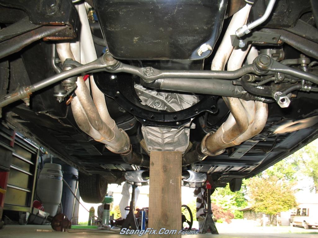
Well it's been awhile in the making and I'm setting some time aside to create a thread on this, as I'll likely need tips as I proceed. The car is a 70 Mach with a 351w and an FMX trans that leaked out of every crevice possible. Below is a parts list, prices paid, and some pictures of those parts. I set out try and save money where I could in order to get a few more comforts like hydraulics. My goals for this project are to minimize the changes to the car that can't be reversed easily, such as hacking up the trans tunnel to fit the beast in there. My wife is due August 15th with our first child, so I'll be hauling balls trying to get this conversion complete.

Parts List thus far:

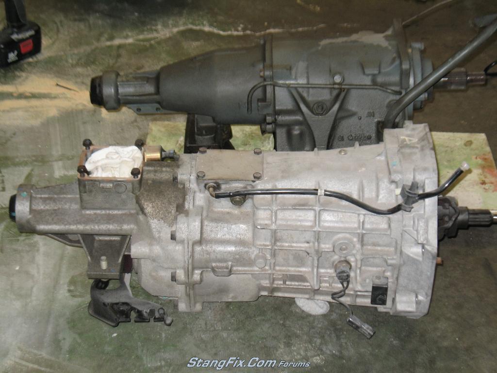
2004 Cobra T-56 used with 29k miles - $900
Quicktime RM-8031 Bellhousing new - $350 from Corral.net group buy
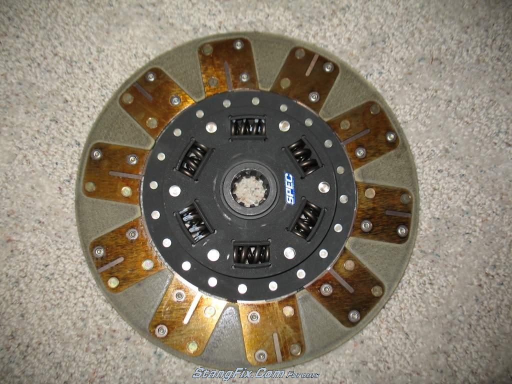
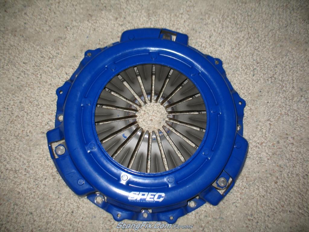
Spec Stage II SF482 kevlar clutch and pressure plate -- Slightly used (one run on dyno) -- $190 from Corral.net classifieds
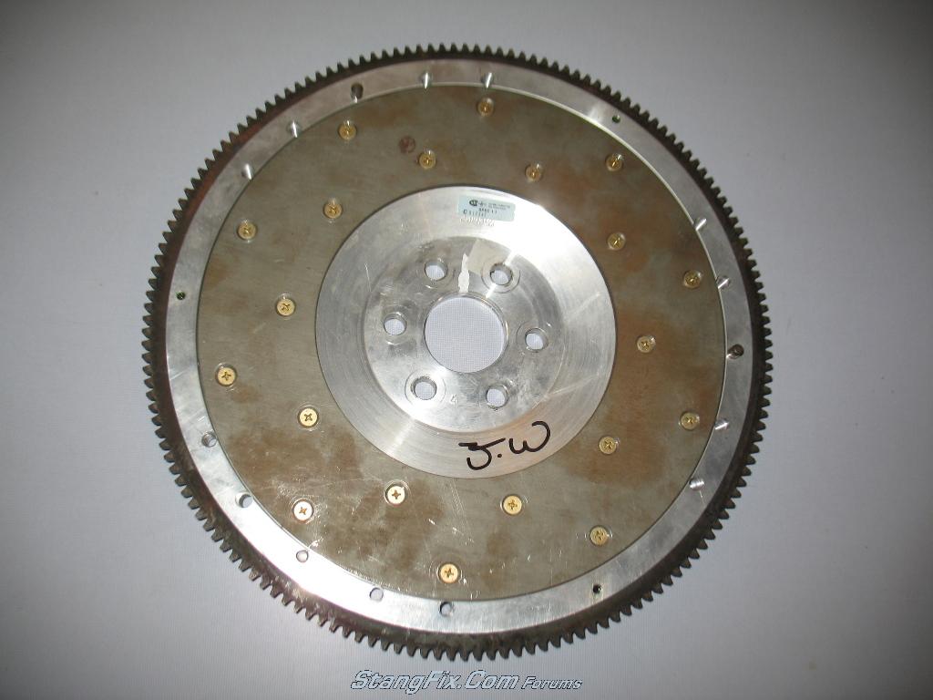
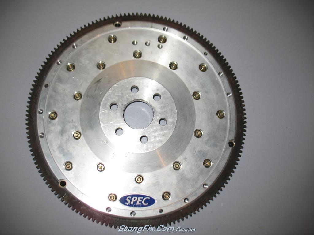
Spec SF05A billet aluminum flywheel (yes I know DD negatives with lightweight flywheels) -- New in box -- $250 from Corral.net classifieds
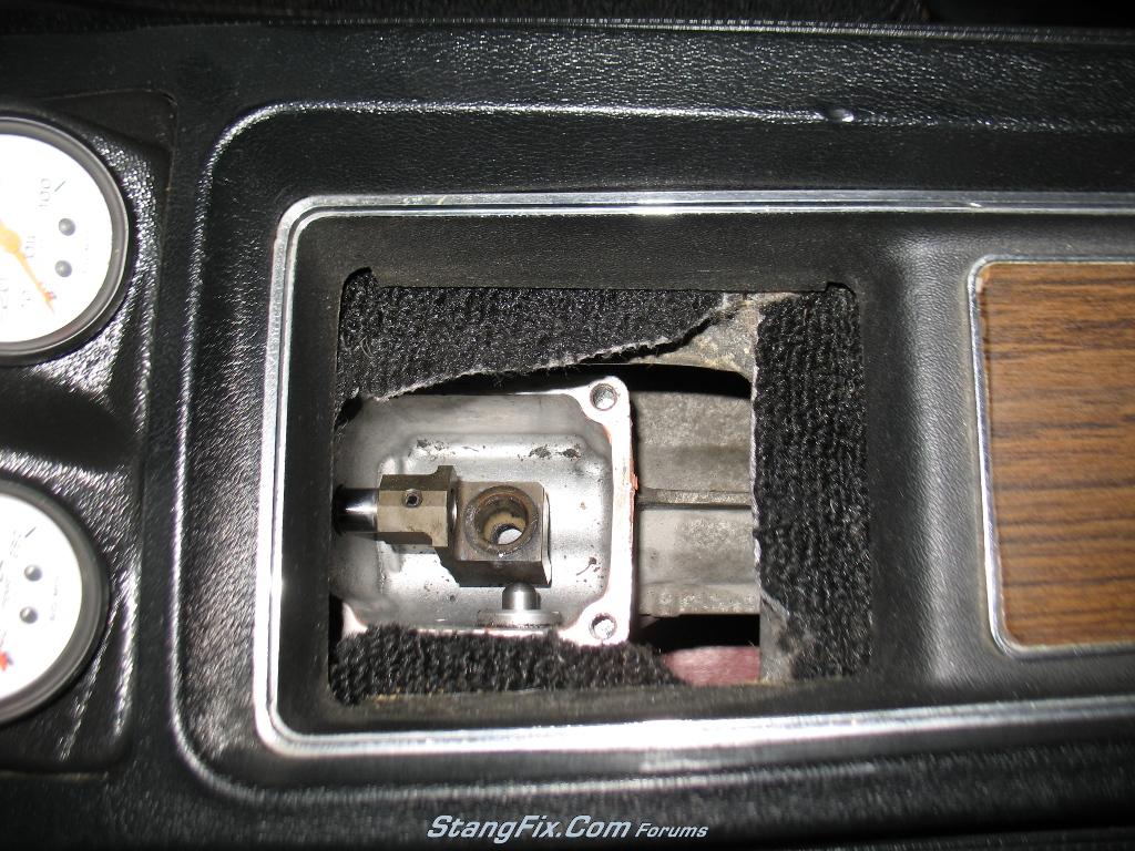
Pro 5.0 billet shifter with Steeda Tri-Ax shifter -- Slightly used -- $75 from SVTPerformance.com classifieds
Hurst white 6spd shifter ball - $30
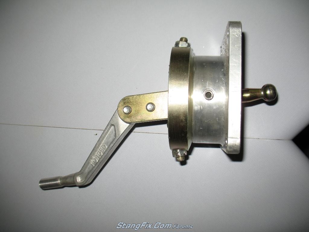
Cobra slip yoke used - $50
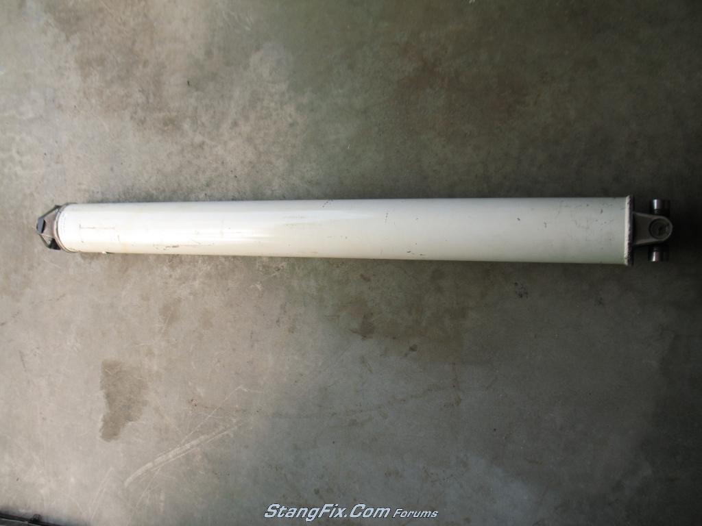
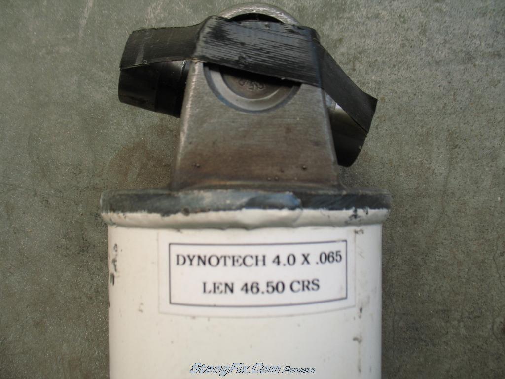
Dynotech 46.5" x 4" x 0.065" steel driveshaft used from NASCAR - $38 shipped
Mustang original clutch pedal assembly - $170 shipped
MustangSteve roller bearing kit - $40
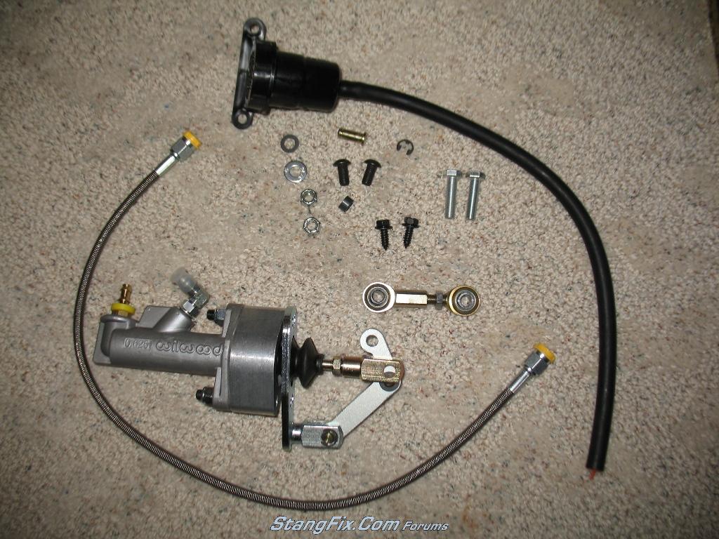
ModernDriveline LF Master Cylinder kit - $235
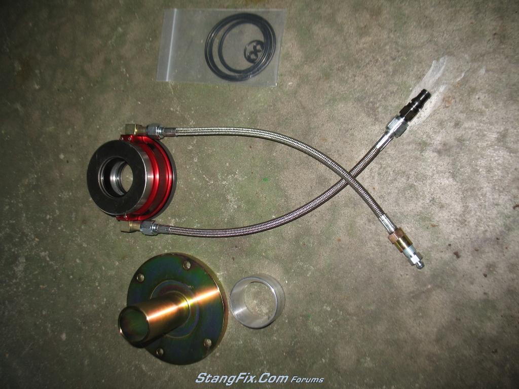
McLeod 14-301 Hydraulic Throwout bearing with sleeve - $486 :scar :scar
24" stainless hydraulic line - $39
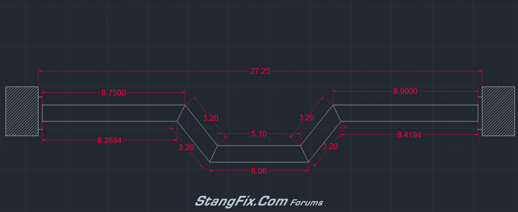
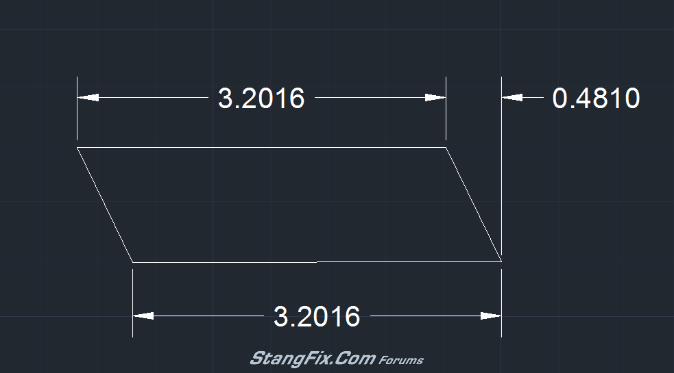
3"x1"x1/8" rectangular tubing 4' long for the custom trans crossmember - $30
Custom motor mounts - roughly $50 See build thread here: http://www.stangfix.com/testforum/index.php/topic,6383.0.html
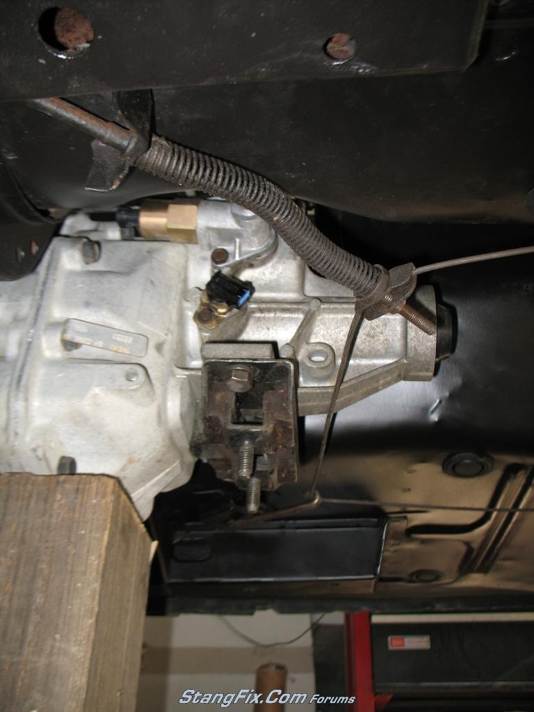
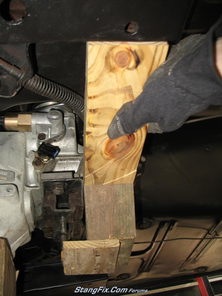
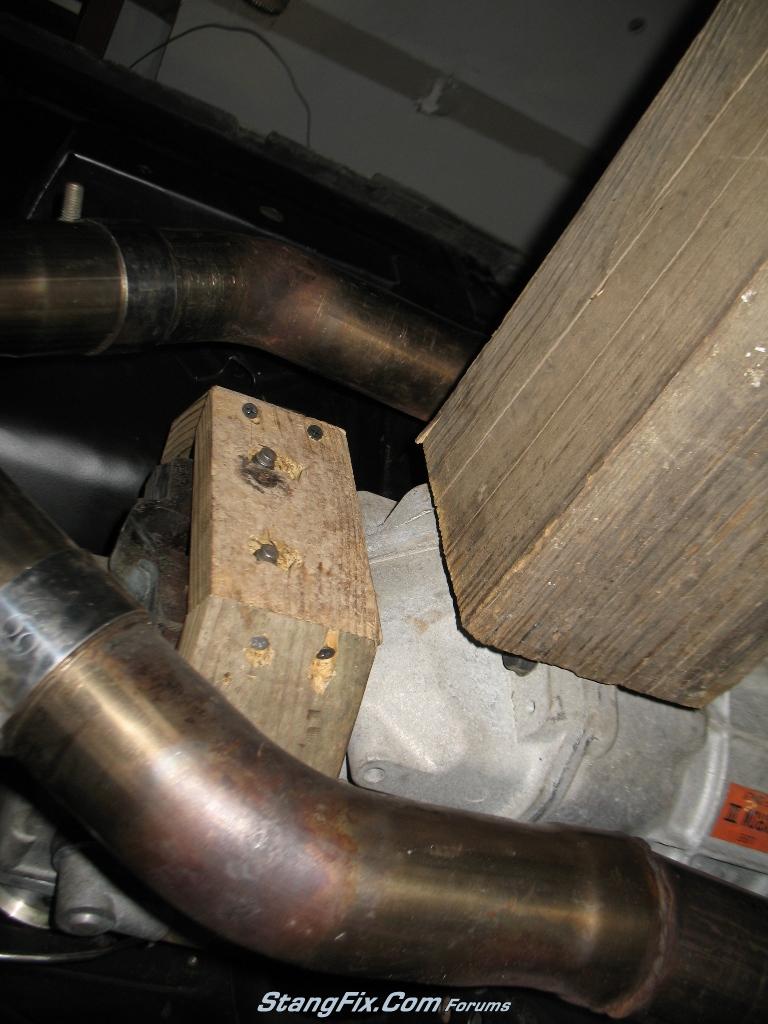
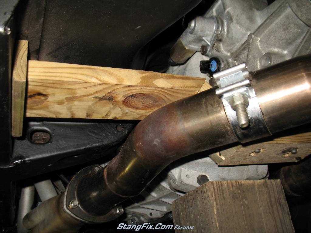
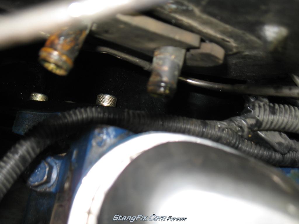
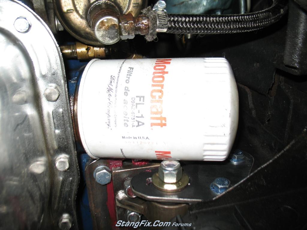

Pictures:

231_24_05_10_4_38_20_0.jpg


231_24_05_10_4_38_21_3.JPG


231_24_05_10_4_38_21_4.JPG


231_24_05_10_4_38_20_1.JPG


231_24_05_10_4_38_20_2.JPG


231_24_05_10_4_40_15_0.JPG


231_24_05_10_4_47_02_0.JPG


231_24_05_10_4_47_02_1.JPG


231_24_05_10_4_40_15_1.JPG


pic4.jpg


231_24_05_10_5_00_10_0.JPG


231_24_05_10_5_00_12_1.JPG


Thats all for the parts list. I'm up to about $2900 for everything including miscellaneous ARP bolts and other hardware.
 
Last edited by a moderator:
With the FMX, exhaust, headers, steering linkage, brake booster and M/C, tires removed, and car on jack stands and fully level in all directions, I am ready to bolt up the bellhousing and transmission and jack it into the tunnel. With the stock motor mounts still in place, I am getting a little over 6° at the tailshaft of the T56. The inspection cover on top of the trans is touching the trans tunnel support when this angle was measured. With the rear axle supported so that the suspension is fully loaded, I am amazingly getting 0°. This means that you would end up with 6° driveline angle with stock motor mounts and the trans touching the tunnel. You will definitely need drop motor mounts or hack up the trans tunnel with this transmission. Also, note the picture below that shows the location of the shifter and the shifter opening. Sliding the motor back will better align the shifter in the opening.


231_24_05_10_5_13_45_1.JPG
 
Last edited by a moderator:
I have since removed the stock motor mounts and installed the custom motor mounts. With the stock mounts in place, I was measuring 24" from the concrete to the oil pan bolt head nearest the mounts. I am now measuring exactly 23", so all of my measuring and drawings indeed created a full 1" drop. Sliding the motor back was a royal PIA! I thought I'd be smart and grease up the motor plates so that I could just jack up the tail of the trans and slide it all back. WRONG! I had to jack up the motor as well so that the entire motor and trans floated on two jacks, in which then I slide the motor back. A cherry picker would have accomplished the same, but I don't have one of those and this worked just as well. Initially I had planned on sliding the motor back a full 1.5". Why?? A few reasons. With the deal I got on the $40 driveshaft, it was 1.5" too short with the motor in the stock location and getting 0.75" slip yoke play. It would also give me more clearance for a better radiator fan.

One would think that 1.5" doesn't seem like much, but when you are moving an engine back that far it seems everything gets in the way. To start out, my car has the factory A/C. This means that the heater core tubes are close to the head and one is actually behind the head.
231_24_05_10_5_30_47.JPG


Another clearance issue was the power steering pump hard line that comes out the back of the pump. The further you move the engine back, the closer the oil filter gets to the shock tower. Fortunately I didn't go to that extremes but if it were a problem an oil filter relocation kit would have fixed that. I need to flip that motor mount bolt so the nut doesn't touch the filter.

231_24_05_10_5_49_26_1.JPG


Finally, one that I had not expected was the sway bar. When the wheels are suspended off the ground, the sway bar touches the crank pulley. This is the 3 sheeve pulley, so one may not run into problems with a different setup. On the ground there is plenty of clearance, but I need to consider it could cause issues if I ever go over a hill too fast and get the wheels close to coming off the ground. An aftermarket sway bar may alleviate this issue, or it could make things worse. With all factors considered, I was able to move the engine back 1.25".

Clearances check at the steering center link, steering ram, and idler arm. I will have to dimple the header for the steering box, which was dented previously for that reason but moving it back means I need to create a new dent. Exhaust clearance at the trans tunnel support is fine :ecit When I had the exhaust installed, the collector reducers were touching the tunnel support so we had to dent the reducers as can be seen in the pic.

231_24_05_10_5_47_58_0.JPG


231_24_05_10_5_48_01_1.JPG


231_24_05_10_5_48_02_2.JPG


231_24_05_10_5_48_03_3.JPG


231_24_05_10_5_48_06_4.JPG


231_24_05_10_5_49_26_0.JPG


231_24_05_10_5_49_26_2.JPG

With everything slid back, I then installed the steering linkage and exhaust to check for clearance issues with those. With this drastic of changes ya never know!
 
Last edited by a moderator:
Next up is the transmission crossmember. For what it's worth, I found out that the stock FMX (and other Ford trans) rubber isolator bolts up perfectly to the T56! :) This will make things much easier in terms of an isolator.

From another thread on here, I was asking about any aftermarket other than Lokar parking brake cable kits. As you can see, the cable end is right in the way of the xmember as well as the cable is touching the tailshaft of the trans

231_24_05_10_6_32_00_0.JPG


Early version of the xmember:

231_24_05_10_6_32_01_1.JPG


I removed the drivers side bracket for the parking brake cable and have the wooden Xmember in place. I decided against the above picture setup with a plate welded to the bottom of the 3x1 due to the X-pipe converging at this location. I'll have to open up the bottom of the 3x1 so that I can put nuts on the isolator bracket, since the bolts aren't long enough to go through the 3x1.

I'm taking these pictures on my back, so bear with me on the angles :scar

231_24_05_10_5_49_26_3.JPG


231_24_05_10_5_50_34_0.JPG


231_24_05_10_5_50_34_1.JPG


231_24_05_10_5_50_35_2.JPG


231_24_05_10_5_50_35_3.JPG


I have about 1/4" or slightly more clearance from the exhaust to the Xmember. Hopefully that ends up being enough.
 
Last edited by a moderator:
While messing around with the Xmember, I happen to notice that the transmission was not level (side to side). This concerned me, since I had custom motor mounts and thought I had it all correct. So I bust out my tape measure and start taking measurements. At the front left corner of the oil pan, I measure 22 7/8". At the front right corner I measure 22 13/16". Within 1/16" which could be measuring errors, so call it good. I go to the rear left corner of the oil pan and measure 22 1/8". At the rear right corner I measure 22 3/16". Again, within a 1/16" so the motor is level at the front and rear. A quick check with a level on the oil pan confirms this. At the flange of the bellhousing where the trans attaches is where it gets whacky. On the right side bottom of the flange I measure 15 1/2". On the left side I get 15 3/16". That is over 1/4" difference in about 5" of length. if this were the width of the oil pan it'd probably be well over 1". Pictures are below.

231_24_05_10_6_12_40_0.JPG


231_24_05_10_6_12_40_1.JPG


231_24_05_10_6_12_41_2.JPG


As you can see with the picture of the level, its way out of whack. The other two pictures make it harder to tell but it's obvious under the car. I sent an email to Quicktime asking them what could be the issue. It really isn't cause me any problems yet, it just looks goofy. The crossmember center section wouldn't end up being level either. This bugs the crap out of me. Anyone have any suggestions??? I'm pretty much stuck up to this point :cry :cry
 
Last edited by a moderator:
I noticed a similar tendency when I put the T5 in my car. Looked like it was twisted to the right just like yours.

I'll see if it's any different when it goes back in when the engine is finished.
 
Very cool. Dig the wooden crossmember! :lol Looks like 10lbs of crap in a 5lb bag though...looks like it's tighter than a you know what's you know what!

PS: How's the weather out there? I'm set for a flying trip through Bloomington on Saturday and I dunno if I should pack my long johns. :lol
 
"Sluggo" said:
I noticed a similar tendency when I put the T5 in my car. Looked like it was twisted to the right just like yours.

I'll see if it's any different when it goes back in when the engine is finished.

Please do!! What bellhousing are you using??
 
"gotstang" said:
Very cool. Dig the wooden crossmember! :lol Looks like 10lbs of crap in a 5lb bag though...looks like it's tighter than a you know what's you know what!

PS: How's the weather out there? I'm set for a flying trip through Bloomington on Saturday and I dunno if I should pack my long johns. :lol

:lol :lol yeah I figure it's easier for me to work with wood and get all the lengths and angles somewhat close, then bust out the steel and such. What sucks is I can't squeeze the crossmember into place once it's all welded up unless I drop the exhaust. Definitely 10lbs of crap in a 5lb bag!

Weather is friggin humid. I thought it'd be a good idea to take a day off work to mess with the stang and it was 92° and felt like it was over 100 thanks to the humidity. Supposed to be 90+ all week so pack the shorts!
 
"buckeyedemon" said:
did you get a measurement of the engine angle and driveshaft angle with your drop mounts installed?

I'm setting right at 3° and have over 1/4" clearance from the top inspection cover bolt head to the trans tunnel support. I know 68EFIVert only used 1/2" drop mounts and got his to about 3.5° IIRC
 
3° angle difference between the transmission shaft and the rear axle pinion. Basically put an angle gauge on the trans shaft that sticks out the end of the trans, which ends up being pointing down from the horizontal 3°. The rear axle pinion is ironically exactly level so the driveline angle just ends up being the trans pointing down. The driveshaft angle doesn't mean much, its the difference between pinion and transmission shaft.
 
i completely disagree with your statement about the drivehaft angle being irrelevant. i could draw you a picture of an engine 3 degrees down and a pinion at zero degrees that would eat universals.

i'm fine with the whole pinion angle needing to be close to equal and opposite, but you also want to minimize the working angle of your u-joint. thus you need to measure your driveshaft angle.
 
Well I heard back from Quicktime already!!! Below is their response:

All T56's are clocked 5 degrees counter clockwise for the fork to work in the OEM cars.

So, it appears that I was worried about nothing as they are that way from the factory apparently.
 
"buckeyedemon" said:
i completely disagree with your statement about the drivehaft angle being irrelevant. i could draw you a picture of an engine 3 degrees down and a pinion at zero degrees that would eat universals.

i'm fine with the whole pinion angle needing to be close to equal and opposite, but you also want to minimize the working angle of your u-joint. thus you need to measure your driveshaft angle.

The factory driveline angle is within 3° so I'm not out of spec from the factory, but the driveshaft is 3" shorter. This means that the driveshaft angle will be slightly larger than the original setup. Once I get the driveshaft installed I'll measure it's angle. What is the max driveshaft angle typically? This is a first I've heard of checking on cars, raised trucks are a different story. Thanks for the heads up.
 
here is a very, very simple read on the issue. minimize the u-joint working angle to preserve life and keep ~equal and opposite to minimize vibrations.

http://www.hurst-drivelines.com/files/Universal_Joint_Alignment_Proc_111606.pdf

this seems to be an often confused topic. i commonly read people reference that the engine angle is 3 degrees. but with respect to what? if you had big balloons for rear tires, the number will be different than someone with small rear tires. just an example.

fwiw, this is straight from the 69 chassis assembly manual.

a 69 mustang 351W manual or auto

engine angle: 4*7' down
driveshaft angle: 2*29' down
pinion angle: 1*17' down

resulting engine/driveshaft u-joint angle: 1*33'
resulting pinion/driveshaft u-joint angle:3*46'

i'm curious to know what you have. i did a transmission swap but mine is only a shell and couldn't get a driveshaft angle measurement. all i know is that increased the engine angle on the order of 0.25 to 0.50 degrees as measured directly before and after the swap (351W, drop mounts, TKO, notched floor support, slight cut to the transmission tunnel and my own transmission mount).

it's very rare that anyone will publish these values.
 
Good info, especially the stuff from the chassis manual! A little caveat with my angles, the rear suspension is loaded on jackstands so that I get the correct angle but the front of the car is not on the suspension. This means that my measured pinion angle of 0° would not be the same if the front suspension were loaded. But, since the rear axle is loaded it still provides the correct reference point in order to check the driveline angle. I chose to not load the front suspension so that I could level the entire car to ensure everything checks out with the custom motor mounts and trans crossmember.

I don't have anything accurate enough to measure to the minutes, only degrees. I also still need to buy the conversion U-joint for the rear. The slip yoke is 1350 from the Cobra and the driveshaft has 1350s front and rear. Once I get the conversion U-joint I will get you a driveshaft angle :) I just have to find one that has the special 1 1/16" cap at the pinion and the 1350's 1 3/16" cap diameter. After a little research, I may just end up buying the 1350 pinion yoke and be done with it. It'll be about the same price as the conversion u-joints.

Here another good link for others curious about driveline angle:

http://www.drivetrain.com/parts_catalog/drivetrain/driveline_angles_and_phasing_problems.html
 
Now that the indexed bellhousing/transmission issue is settled, its time for some trans crossmember fabrication. Using my extremely precise wood template as shown in previous pics, I took measurements from those pieces as well as the inside distance from frame rail to frame rail and headed off to draw it up on AutoCAD. I'm a tech geek and do drafting at work sometime, so it's a bit second nature. Below are screen images of the crossmember drawn up and dimensioned, as well as a detail for the diagonal pieces in order to cut them out correctly. All other pieces are self explanatory when cutting.

231_25_05_10_5_53_26.png


231_25_05_10_5_39_41.png
 
Last edited by a moderator:
Back
Top