• Hello there guest and Welcome to The #1 Classic Mustang forum!
    To gain full access you must Register. Registration is free and it takes only a few moments to complete.
    Already a member? Login here then!

Fitting stainless headers

Hi all,

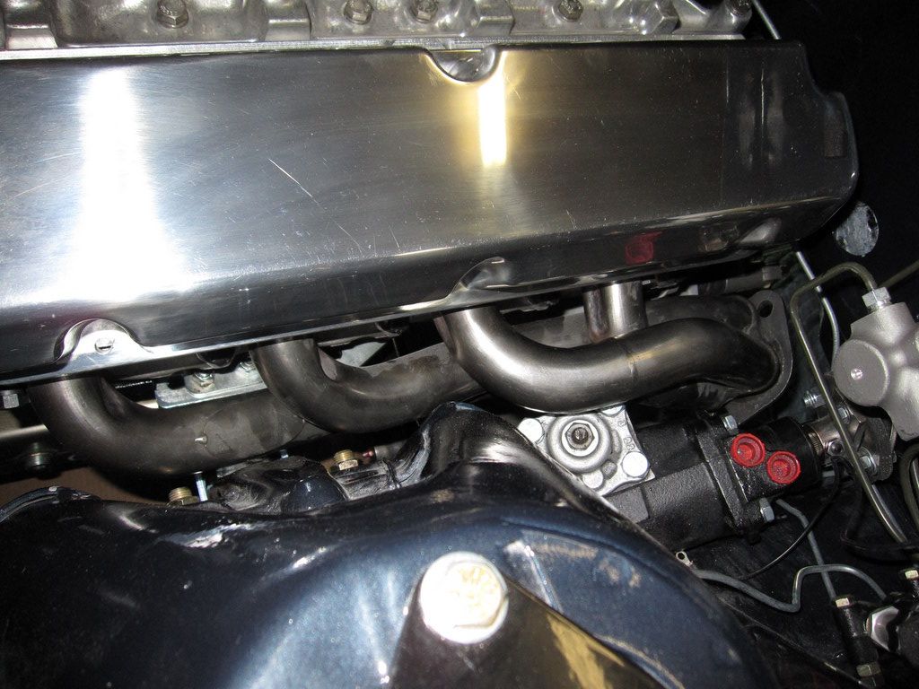
I'm trying to fit my JBA shorty headers to my 65 vert (with a Borgeson p/s conversion) and .. big surprise.. I'm running into fitament issues.

I 've got the Ron Morris engine mounts and that's allowed me to push the engine back and lower it a bit.. but the header is still hitting the steering gear in one place.. I'm thinking that I could shave a little off the steering gear and dent the header a bit and I'll be golden.

Any tips on how to dent stainless headers so that I don't crack them?

Can't say enough good things about the Ron Morris mounts. They rock.

Thanks in advance!

-Shannon
 
You've got to post some pictures. I have thought using the Borgeson in mine and would really like to see what you are running into. I'm sure there are others interested as well. Thanks
 
Well.. I got them to fit for the most part without denting. As I said before I couldn't have done this without the RM engine mounts. With them I was able to push the engine probably a 1.5 inches back. Normally, I wouldn't have been able to push the engine so far back because the emergency brake bracket on the transmission cross member wouldn't allow me. But as luck would have it, I relocated the e-brake to the tunnel between the seats so I was able to remove the bracket. I did not end up using the engine mounts that lower the engine a 1/2".

I still might go ahead a dent the headers in two places: the drivers side at the steering gear and the passengers side at the shock tower. Normally the shock tower wouldn't have been a problem, but I had welded in extra supports. I've got about 1/8" clearance in both places, but I think I need a little more because of the movement of the engine while running.

As far as the transmission goes (a T5z).. again because I was able to push the engine back, the shifter fits perfectly in the stock hole without trimming.

I haven't taken pics yet, but I'll try to have some up tonight. I'm really glad that this part of the build turned out so well, I've been stressing over it for weeks.

There is one casualty of this mess... the engine cross member. Since I pushed the engine back so far the cross member now hits the oil pan. Anyone have any ideas on how to make one????

-Shannon
 
Here are some pics:

2011-04-15_-_Engine_installed_005.jpg


2011-04-15_-_Engine_installed_002.jpg


2011-04-15_-_Engine_installed_003.jpg


2011-04-15_-_Engine_installed_001.jpg


2011-04-15_-_Interior_003.jpg
 
Last edited by a moderator:
"LastDeadLast" said:
There is one casualty of this mess... the engine cross member. Since I pushed the engine back so far the cross member now hits the oil pan. Anyone have any ideas on how to make one????

Welcome to the club! I still need to make one as well. I bought the 2" square tubing, I just need to mock it up and weld it together. I plan on mimicking the Cobra Automotive version that ties the shock tower/LCA bolts to the crossmember. Theirs is made of round tubing, but is a pain to work with IMO when DIYing something without a bender or notcher.

crossmember.jpg
 
"buening" said:
Welcome to the club! I still need to make one as well. I bought the 2" square tubing, I just need to mock it up and weld it together. I plan on mimicking the Cobra Automotive version that ties the shock tower/LCA bolts to the crossmember. Theirs is made of round tubing, but is a pain to work with IMO when DIYing something without a bender or notcher.

crossmember.jpg

I've got some 2" square tubing too... but I haven't started this project yet.

I installed eccentric adjustments for my LCA bolts.. so I can't do the Cobra Automotive version.. unless I can figure out how to make the mounting adjustable to correspond to the LCA bolt location.

I was thinking about welding in a another place to bolt up the crossmember on the bottom of the frame.. that way it would have two attachment points on each side instead of one... probably just wasting my time since it would be in the same plane.

thoughts?

-Shannon
 
Well you wouldn't HAVE to tie the crossmember to the LCA but it is ideal. I too will have the eccentric plates with regular bolts instead of the round eccentric bolts, so I'll have to figure this out as well. I haven't thought this far, but you could transfer the plate retainer to the crossmember for the rear of the LCA. The front obviously stays where it is. The hole in the crossmember LCA location is slotted for camber adjustment.

Here is a link to the Boss 302 Chassis Mod manual, and on Page 8 it shows the mods to the stock crossmember. It doesn't really show the eccentric washers, but maybe I'm missing something. http://www.mustangtek.com/Library2/BOSS ... isMod.html

Edit: The text in the Boss manual states that camber is now adjusted by shimming the UCA. Surely something can be worked out by keeping the LCA adjustable. Anyone have any thoughts?
 
Applejack, from the VMF and Corner Carvers forum, has a post on the VMF a couple times about making his own and how he was going to deal with the eccentric plates:

I plan on making my own crossmember with exactly the same shape hole.

The idea is to use the square eccentrics from Pro-Motorposrts. That way I can still get camber adjustment. I'll use a spacer of the correct length between the eccentric and the cross-member with a longer G8 bolt.


So from what I can tell, you have the eccentric plates installed as normal as if there isn't a crossmember there. Then you use a spacer tube between the eccentric plate and the crossmember. The bolt that projects through the crossmember just has a washer and nut. Make sense?
 
"buening" said:
Applejack, from the VMF and Corner Carvers forum, has a post on the VMF a couple times about making his own and how he was going to deal with the eccentric plates:

I plan on making my own crossmember with exactly the same shape hole.

The idea is to use the square eccentrics from Pro-Motorposrts. That way I can still get camber adjustment. I'll use a spacer of the correct length between the eccentric and the cross-member with a longer G8 bolt.


So from what I can tell, you have the eccentric plates installed as normal as if there isn't a crossmember there. Then you use a spacer tube between the eccentric plate and the crossmember. The bolt that projects through the crossmember just has a washer and nut. Make sense?

Sounds easy enough. I'll probably be starting that project this weekend. I'll be sure to take lots-o-pics.

Thanks for the info!!

-Shannon
 
Back
Top