Mach1 Driver
Well-Known Member
I've been having discussions on two other forums (some with Midlife) and thought I'd share what I've learned.
I wrote:
If it were me, I would get rid of the original gauge constant voltage regulator, and replace it with a modern electronic one. The old ones try to provide around 5v by pulsing 12v on about 42% of the time and off about 58% of the time. Since the gauges are dampened it doesn't affect the readings. The new electronic regulators give a rock solid 5v. Edit, for reasons mentioned below*, I have revised my opinion about electronic IVRs.
Just for some background information; Ford intentionally developed gauges that take time to react- they call this dampening. This is so the gauge doesn't bounce all over when you take a curve or do a jump like the General Lee. All the gauges are reportedly the same except for the scale. Even though the oil sender measures pressure and the water sender measures temperature, and the fuel measures fluid level, all three sensors are just variable resistors that read from 78 ohms on Low to 10 ohms on Hi. The gauges have high and low adjustments, and an internet search turned up this information. What he is saying below is that the top adjusts the low end of the scale and the bottom adjusts the high end of the scale. Within some (unknown) "range" they are all adjustable.
2007 jonsee on allfordmustangs said:
Yes there are two adjustments on the back of the three gauges, oil, temp, and fuel - the adjustment on the top is to adjust the zero at 70 -73 ohms and the bottom adjustment is to adjust the 100% reading (better known as the span) at 10 ohms - with 5 -6 volt supply, an increase in resistance decreases current flow through the gauge (better known as indicator) which decreases the reading and a decrease in resistance, increases current flow through the gauge increasing the reading.
And then this morning there was more, I wrote:
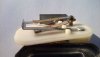
I just saw this great picture courtesy of Jharcinske on VMF. Ford developed a gauge that doesn't use the typical D'Arsonal meter movement. It is a bi-metal device with a heater to make it move. That's why these things have so much dampening- its inherent in the design, and probably costs much less than a typical meter movement. A little more explanation is probably in order here: a bi-metal is two sheets of dissimilar metal formed together in layers like a sandwich. They use materials that have greatly different expansion rates. When heat is applied they bend, because one side expands faster than the other. The bending is very predictable and repeatable.
In the same thread (about gauges) I got a response from TheRktmn who owns a gauge repair shop. I asked him about the the two adjustments and he responds:
They set the high and low points for the gauge. You will need a face on there to do it, but with a 73 ohm resistor for low and a 10 ohm resistor for high and a 5VDC power supply you can set the gauge back to factory specs.
Use a small screwdriver in through that hole to engage the teeth and move the arm. You will see the pointer move.
Once you change one you need to check the other since it will change some too.
* Edit: it has come to my attention that the electronic IVRs do not properly mimic the operation of the old electro-mechanical ones. The electronic versions put out a nice constant 5v, which is good most of the time. It is my "theory" that the old electro-mechanical versions put out 12v for a short period of time at start-up, probably less than 5 seconds, before they start pulsing to give an average 5v. This allows the instruments to quickly reach their operating range. People with electronic IVRs report delays of 30-40 seconds before the instruments are up to their operating ranges. That isn't a problem with most of the instruments, but many people with expensive engines want to know they have oil pressure before 40 seconds. I suspect that if the manufacturers knew it was problem they would work to correct it.
I wrote:
If it were me, I would get rid of the original gauge constant voltage regulator, and replace it with a modern electronic one. The old ones try to provide around 5v by pulsing 12v on about 42% of the time and off about 58% of the time. Since the gauges are dampened it doesn't affect the readings. The new electronic regulators give a rock solid 5v. Edit, for reasons mentioned below*, I have revised my opinion about electronic IVRs.
Just for some background information; Ford intentionally developed gauges that take time to react- they call this dampening. This is so the gauge doesn't bounce all over when you take a curve or do a jump like the General Lee. All the gauges are reportedly the same except for the scale. Even though the oil sender measures pressure and the water sender measures temperature, and the fuel measures fluid level, all three sensors are just variable resistors that read from 78 ohms on Low to 10 ohms on Hi. The gauges have high and low adjustments, and an internet search turned up this information. What he is saying below is that the top adjusts the low end of the scale and the bottom adjusts the high end of the scale. Within some (unknown) "range" they are all adjustable.
2007 jonsee on allfordmustangs said:
Yes there are two adjustments on the back of the three gauges, oil, temp, and fuel - the adjustment on the top is to adjust the zero at 70 -73 ohms and the bottom adjustment is to adjust the 100% reading (better known as the span) at 10 ohms - with 5 -6 volt supply, an increase in resistance decreases current flow through the gauge (better known as indicator) which decreases the reading and a decrease in resistance, increases current flow through the gauge increasing the reading.
And then this morning there was more, I wrote:
I just saw this great picture courtesy of Jharcinske on VMF. Ford developed a gauge that doesn't use the typical D'Arsonal meter movement. It is a bi-metal device with a heater to make it move. That's why these things have so much dampening- its inherent in the design, and probably costs much less than a typical meter movement. A little more explanation is probably in order here: a bi-metal is two sheets of dissimilar metal formed together in layers like a sandwich. They use materials that have greatly different expansion rates. When heat is applied they bend, because one side expands faster than the other. The bending is very predictable and repeatable.
In the same thread (about gauges) I got a response from TheRktmn who owns a gauge repair shop. I asked him about the the two adjustments and he responds:
They set the high and low points for the gauge. You will need a face on there to do it, but with a 73 ohm resistor for low and a 10 ohm resistor for high and a 5VDC power supply you can set the gauge back to factory specs.
Use a small screwdriver in through that hole to engage the teeth and move the arm. You will see the pointer move.
Once you change one you need to check the other since it will change some too.
* Edit: it has come to my attention that the electronic IVRs do not properly mimic the operation of the old electro-mechanical ones. The electronic versions put out a nice constant 5v, which is good most of the time. It is my "theory" that the old electro-mechanical versions put out 12v for a short period of time at start-up, probably less than 5 seconds, before they start pulsing to give an average 5v. This allows the instruments to quickly reach their operating range. People with electronic IVRs report delays of 30-40 seconds before the instruments are up to their operating ranges. That isn't a problem with most of the instruments, but many people with expensive engines want to know they have oil pressure before 40 seconds. I suspect that if the manufacturers knew it was problem they would work to correct it.
Attachments
Last edited: