
67resto-coupe
Member
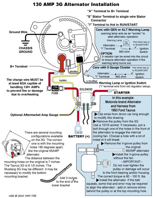
3G Upgrade to my '67 notchback. I'm almost done wiring a junkyard '00 Taurus 130a 3G. I got a new factory alt harness. Wired a new plug onto the S wire for the power input connection and added an ring connector to the "A" yellow wire to run into the power stud. But now I am STUCK on how to wire the green/red wire coming out of the "I" harness port.
I've read that the 3G alts are "self-exciting" and just to blip the throttle to get the alternators started. Then I've read that the green/red wire needs to be connected. ?????
1 - Do I need to connect it? If so, can someone tell me EXACTLY where to splice? I've read the "I" post on the solenoid, but not sure.
2 - Can I leave it off if the alternator is in fact self exciting?
Also, I believe I'm supposed to ground this new alternator, but there's no stud to attach a ground wire. There are a couple of threaded holes on the back of the case, so I'll just figure to take it to the local hardware store to see what size metric bolt or stud will fit. Anyone keen as to the stud size?
I'm a novice with electrical stuff and have a hard time making sense of all the diagrams. I appreciate the help.
-Jeff

POIYw~~_12.JPG)
Nh!~~60_12.JPG)