• Hello there guest and Welcome to The #1 Classic Mustang forum!
    To gain full access you must Register. Registration is free and it takes only a few moments to complete.
    Already a member? Login here then!

Anyone know how to make Dynamite sticks?

You are using a computer power supply? Try using a battery - power supplies can have high frequency noise on them, which might be the problem (ie, triggering the reset). If that doesn't work <shrug>, leave the resistance on the rest (although it should not need it).
 
Hey Apollard, once again I'd like to thank you for your help on my sequential circuit. It works great on the work bench (hooked up to LEDs on a bread board with hand switch). I got both circuit boards soldered up perfectly and I'm curious on how to wire it on my car. My left tail lights wires are like so: Center bulb has 3 wires (dual filament) with a running light wire (Red w/black stripe), brake line wire (green w/ white stripe), and ground..Middle bulb has 2 wires: turn signal wire (green w/ yellow stripe) and ground..Outside bulb has 2 wires: running light wire (red w/ black stripe) and ground..I want my brakes to sequence and also my my turn signals (of course)..I'm definitely gonna need to modify my flasher relay to accommodate for the extended flash rate and maybe use some diodes, but I'd rather get advice on it before accidentally frying something..Help would be greatly appreciated.
 
Here's a close up of one of my circuit boards..Also I put bout 3 layers of liquid tape on the solder joints to prevent shorts.
 

Attachments

  • IMG_0037.JPG
    1.6 MB · Views: 54
Been travelling and out of pocket. How you will wire it will depend on what you are going to use for the lights - LED or incandescent. I used homemade LED arrays(below). It's a lot of work, but I didn't like the look of the aftermarket units I'd seen. Plus, I like doing it myself.
If you use LEDs, use red - you use the same color as the lens for max brightness. I used some high brightness ones on closeout so they were reasonable, but IME get ones from a good manufacturer- the cheap no name ones vary in brightness and burn out - a burned out array can take out the whole segment.
275_22_11_09_3_59_08_1.JPG


Here is how I wired it to my '68:

In order to use LED arrays, you have to do some figuring to determine the correct resistors to use for your array for the brake lights. A good starting place is here:
http://led.linear1.org/led.wiz
The running light resistors will be about 10x that value IME, but the LEDs you use will influence that. Experimentation will be needed here to get the correct value for each set of resistors, so use the above values as starting points. I changed them several times, looking at what they looked like through the lens both night and day.

You will need to isolate the resistors from the arrays to prevent lighting the parking lights on the whole car when the turn signals are on. Simple diodes do that. You can see the dropping resistors for the arrays and diodes on each side of the board at the bottom. Here is how I wired mine(sorry, in a hotel, so ASCII diagram will have to do):

Brake light = Brake/Turn in these diagrams (ran out of room)

Brake light wire ---------------------------------->dropping resistor----> diode----> LED Array 1 anode<---Diode<----dropping resistor<--- park light wire
Brake light wire --> sequencer circuit output 2 -->dropping resistor--> diode--> LED Array 2 anode<---Diode<----dropping resistor<--- park light wire
Brake light wire --> sequencer circuit output 3 -->dropping resistor--> diode--> LED Array 3 anode<---Diode<----dropping resistor<--- park light wire

If using bulbs, you do not need the resistors and diodes:

Brake light wire ----> Bulb 1 brake filament
Brake light wire ----> sequencer circuit output 2 -->Bulb 2 brake filament
Brake light wire ----> sequencer circuit output 3 -->Bulb 3 brake filament
Park light wire----> to park light fliament on all 3 bulbs.

These diagrams of course left out the ground, but obviously each bulb or LED array needs to be connected to ground.

Again, these are for a '68 with a single dual filament bulb, but maybe they will help. I can't help you much on how you would wire this to your setup (A late model car?). But you will need to figure out how to combine the brake/turn signal lines with doides and use that as the feed to the circuit. The problem with using doides with bulbs is that at that current draw, the voltage drop is significant, and the diodes pretty large & expensive (6+ amps needed I'd guess). It would be possible to design a circuit to do this, but it would require a 12V source outside of the turn/brake lights.
 
Last edited by a moderator:
wow that's a lot to take in..I'm using incandescent bulbs for my setup, and I'm gonna need to get 2 more dual filament bulbs and sockets for my tail light assembly (also using a dremel to make the sockets lock in place). This is for a 1995 Acura Integra 2dr but am also makin a set for my buddy's '06 GT, I know you are prolly thinking, "why are you on this website" but I also like muscle cars/trucks. I use to own an '88 short-wheel base f150 but the high gas prices switched me to imports (gets expensive goin to college back and forth). But anyways, if you are still willing to help me out then I'll give you some more info on my car. So my three bulbs going from inside to outer should have a brake/turn signal going into one filament in each bulb and a running light wire into the other filament and of course a ground wire? Bulb one works off the normal turn switch while bulbs 2 and 3 get there juice from the outputs of the module in proper sequence? Is my setup gonna be difficult to wire up like a cobra's sequential tails cause I've been searching online to find that the cobra is a different wire harness setup than GTs and v6, or havin to do with the amber lens? I'm also not quite sure on what you mean by your last paragraph, talkin bout separate battery power sending brake/turn signal, tied together with diodes.. Could you elaborate a lil more on that subject since I won't be using LEDs? At least not yet.. And I'd like to see a vid of your tail lights sequencing cause I'm sure the red is super bright..good job on that by the way
 
That is an ingeniuos way of handling the issue, and would work well. One thing to watch for is that you are not overloading the wiring - 3 1157 brake light bulbs will pull around seven amps when all are lit.
 
yeah it took me forever to find that page bout those DPDT relays. So I should get (2) 10amp DPDT relays to do this mod to handle the ~7amp load? Also I got a replacement flasher relay today that way I could modify it to be able to sequence all three lights, but I opened it up to find only a black box with other TINY timers and what-not..Also, it had one capacitor..I don't believe I would be able to change any resistors in this flasher hence there are none visible. I'm prolly just gonna get another 3 prong flasher relay that FORD makes (with correct B L E positions) and modify that one. I also purchased some FORD dual filament sockets and 3157 bulbs at autozone today..thanks again for all your help!
 
Apollard - what were the specs on the LEDs you used to make your arrays? Do you recall manufacturer and part number? Is it true that you want to get LEDs with the greatest view angle as possible with the highest millicandela rating possible?

Also, what material did you mount your LEDs to?
 
Gonna post replies to some PMs & emails here, so the info is available for others in the future:

I used Cree LC503UHR1-15P. Do a Google search on that and it will pull up a datasheet. Nothing magical about it, I picked it because of the mounting, the intensity, color (you need to use the same color as the lens), and it was cheap from Newark at the time. It looks like it might not be available anymore, but this one might work. It has less intensity, but the viewing angle is 2x as wide – the actual light output is probably about the same. So, it might even work better. http://www.newark.com/cree/lc503uhr1-30 ... dp/02P7159

And, it’s cheap right now. Buy extras, as the failure rate for LEDs is ~1%, and you’ll fry a few. If they make it past the first 10 hours, they are good for a long time. But, some may die.

I used PVC to mount the arrays. I cut PVC pipe to width, split it, and heated to flatten. I then heated it and pressed it against the lens to get the general shape of the lens. By forming it into the lens profile, I got a good fit in the light assembly, and just needed some weatherstrip to pad it - with the w/s in place, it stays where I want it after assembled. I also drilled the holes for the LEDs so that they were pointing directly at the lens. If you drill them perpendicular to the PVC, they will not point correctly and the lens illumination will be uneven. I drilled the holes for a tight press fit.

Here is a rough drawn schematic. I decided my array to get what I thought would be a good even spacing. That turned out to be a 4x6 array (frankly, probably too much, as they are bordering on too bright). You will need to figure out a resistance value for Rx. A good starting place is the LED array wizard http://led.linear1.org/led.wiz . LEDs are very voltage sensitive, so design for the car running voltage (mine is 14.4v, but I run a 3G alt). Also, I did not calculate the array using the max mA the LEDs could handle – this extends the life, as running them right at max current is bright, but will stress them. The wizard will give you a good idea what the starting point is, but I did not use the wiring they show there but only one resistor per array (to allow the park light tie-in).[nb]note that you could wire the array as the wizard shows, and then the parking light resistor would be an additional drop. In my development, I started out as shown in the schematic, so that's how I stayed. [/nb] So, I had to adjust my values to get them to the brightness I wanted in the car (most likely would have anyway, as the blocking diodes cause some voltage drop). Ry for me turned out to be ~10 times Rx. Again, start there and adjust as needed. I can’t remember what values mine turned out to be. The blocking diodes shown are 1N400x types, I used 1N4004 IIRC.

275-200511064113.jpeg
 
Last edited by a moderator:
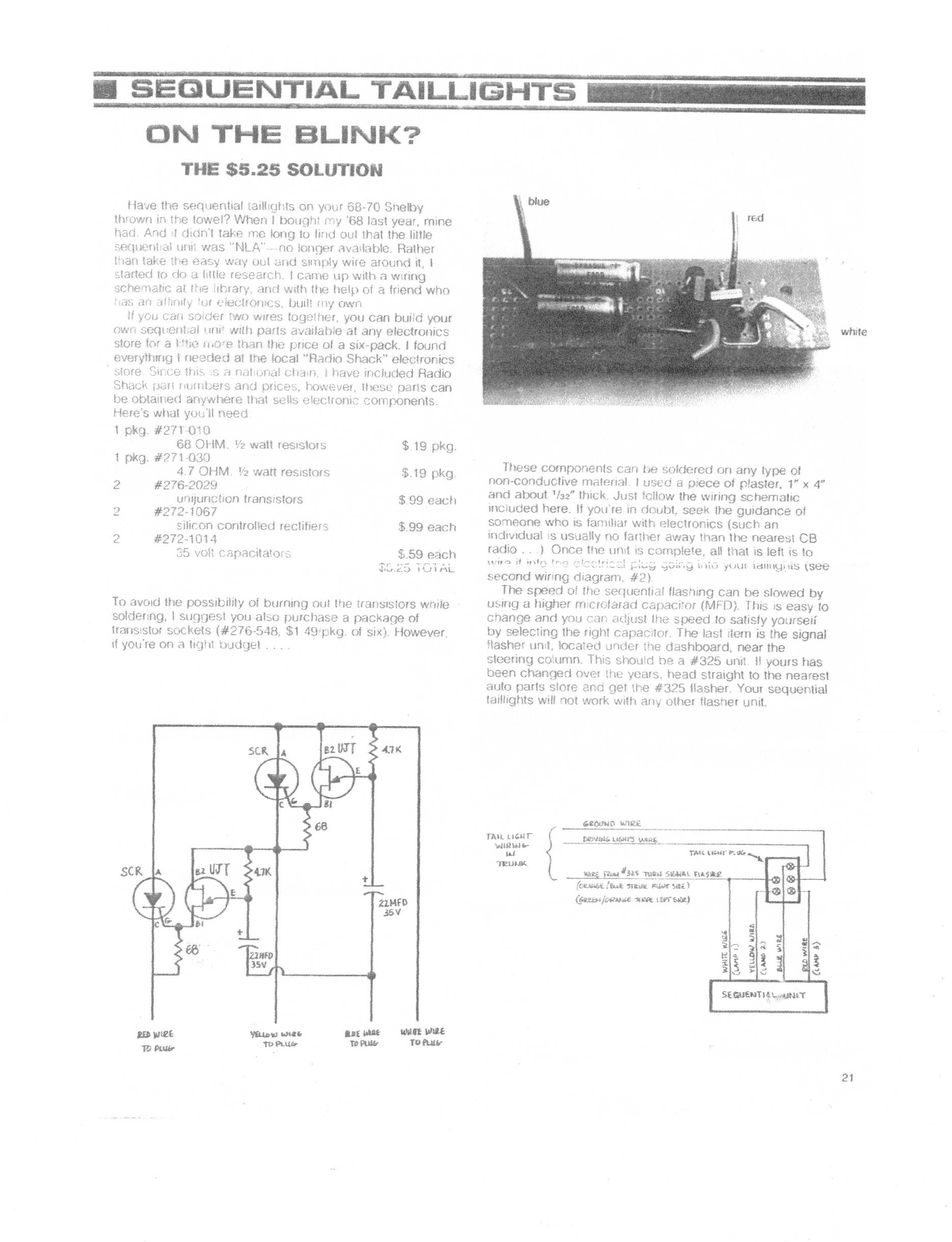
A bit of a necropost, but remembered this post when I was digging through old mustang papers and came across an article on making the sequential relays. I don't know jack about circuits and this may or may not be a good article, but thought I'd throw it up here just in case. The pic is large because the quality of print was pretty poor on the paper

231-160913125444.jpeg
 
Back
Top