LNimoy
Member
I spent the afternoon putting everything back into my dash after the harness install.
When I installed the instrument cluster, I started the car to check the gauges.
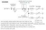
The Oil and Water gauges are not working. They are not pegged in either direction. Needle on both sit at the first line of each gauge. I know they get power from the CVR.
The Fuel gauge shows 1/8 tank. it should be a bit higher with 4 gallons in the tank, but it always read a bit low.
I have an analog multimeter and I checked the CVR and gauges.
I have 12 volts on the BATT side of the CVR and 5.5 volts on the outgoing side.
It has a good ground, shared with the lug with black wire on the back of the cluster.
With all the wires to the gauges plugged in, and the car running, I tested each of the gauges.
Multimeter set to 10V, I probed each post of each gauge.
I am getting 5 volts on each post of each gauge. I believe that this is correct, no?
I am going to check to see if my white/ red and red/white wire for the Oil and Temp gauges are swapped.
I did have to add pigtails under the hood to fix both sending unit wires, they were cracked and frayed near the plug for the sending units.
If I remove the wires from the sending units and ground them and they peg high, my sending units are bad and the wiring from them to the gauges is good, correct?
My initial problem was a severely shorted out under dash harness, Lights were going on by themselves, the car tried starting, without the key in the ignition.
Could that have blown both sending unit, could it have burnt both gauges? Can I test the gauges to determine if they are good?
Thanks,
John


