I received a 1967 harness to restore, and it included a very rare convenience control panel (seat belt, door ajar, hand brake, and low fuel lights). It was missing a sub-harness that connected this panel to the main harness. Documentation was poor, and a resistor wire is part of this sub-harness. I couldn't create the sub-harness without a template to determine the resistor wire value and length of wires. Fortunately, this customer knew someone else who donated his sub-harness to use as a template. The resistor wire was broken or burned up. I consulted the MPC, using a known part number for the low fuel relay, which used the resistor wire. From there, I found other Ford vehicles that used that relay, and consulted the schematics for them. One schematic had a part number for the resistor wire, and found back in the MPC two values: 3.5" and 22 ohms, and 6.5" and 45 ohms. The actual resistor wire was 4" long.
Using the crappy diagrams, I was able to reverse engineer how the relay worked, but needed to determine what was going on in the tank to verify the value of the correct resistor wire. These resistor wires are hard to reverse engineer, because their resistance increases with current flow, so one has to know what's going on throughout the entire circuit to determine the resistance at the proper usage. There is no documentation as to how the low fuel sensor works in Ford's documentation, so I needed access to one.
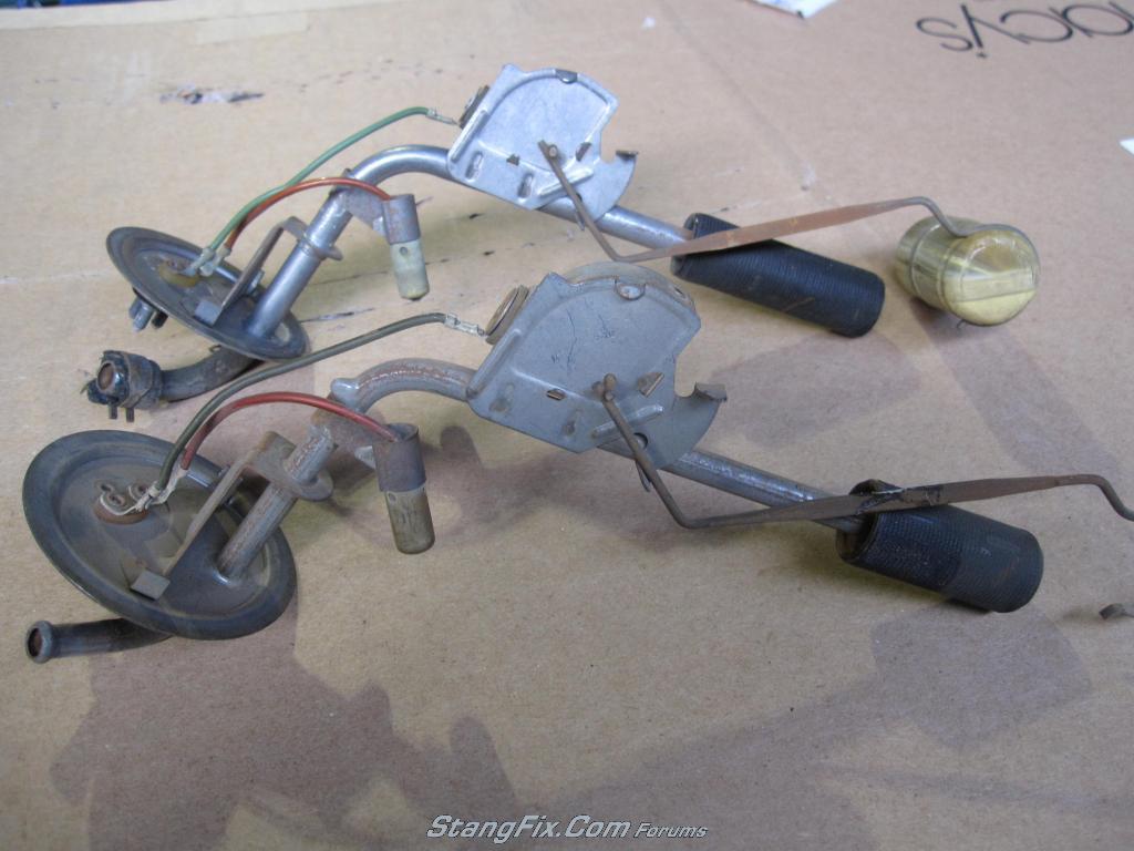
Suddenly, it dawned on me that Craig calibrates fuel sensors and tanks. Aha! A quick phone call to Craig to find out if he had one of these sensors...no. Within 4 hours, he managed to borrow two, shoot me pictures which confirmed my suspicions of how they worked, and will shortly be making precise measurements of resistance of the low fuel sensor itself. It turns out it is a thermistor, which varies as a function of temperature. Huh? You measure fuel capacity by temperature? No quite, but when the thermistor is no longer surrounded by fuel, it's temperature will rise and cause resistance to change (either up or down, depending upon design). I should know all the details shortly. Thanks, Craig! I owe ya one or two!
Using the crappy diagrams, I was able to reverse engineer how the relay worked, but needed to determine what was going on in the tank to verify the value of the correct resistor wire. These resistor wires are hard to reverse engineer, because their resistance increases with current flow, so one has to know what's going on throughout the entire circuit to determine the resistance at the proper usage. There is no documentation as to how the low fuel sensor works in Ford's documentation, so I needed access to one.
Suddenly, it dawned on me that Craig calibrates fuel sensors and tanks. Aha! A quick phone call to Craig to find out if he had one of these sensors...no. Within 4 hours, he managed to borrow two, shoot me pictures which confirmed my suspicions of how they worked, and will shortly be making precise measurements of resistance of the low fuel sensor itself. It turns out it is a thermistor, which varies as a function of temperature. Huh? You measure fuel capacity by temperature? No quite, but when the thermistor is no longer surrounded by fuel, it's temperature will rise and cause resistance to change (either up or down, depending upon design). I should know all the details shortly. Thanks, Craig! I owe ya one or two!