• Hello there guest and Welcome to The #1 Classic Mustang forum!
    To gain full access you must Register. Registration is free and it takes only a few moments to complete.
    Already a member? Login here then!

Lethal289 Build thread - Exploring the 8.8

Re: Lethal289 Build thread

Damn Jake! You got some pretty sweet skills there bro! Very impressive. Look forward to some more of your mods too!
 
Re: Lethal289 Build thread

headjake.png


Just saving the pic for future use. Nothing to see here, move along. :hide
 
Re: Lethal289 Build thread

Do you still have a vintage Mustang?
 
Re: Lethal289 Build thread

ohh yea, had it out today and snapped some new pics. Thats the reason for the new sig!
 
Re: Lethal289 Build thread

Your stang looks great!! Where did you find the bolts with the mustang stamped in? Are they stainless?
 
Re: Lethal289 Build thread

"Triton" said:
Your stang looks great!! Where did you find the bolts with the mustang stamped in? Are they stainless?

Thanks. They are from http://www.gardner-westcott.com/ They are polished stainless steel. I dont see them on the website, but if you request a catalog they have hall kinds, including the v8 and ford symbols too. They are not stamped, they say they are laser etched. Probably so they can charge a little more. lol
 
Re: Lethal289 Build thread - Starting an 8.8

Well, i've looked for a suitable 9" for some time and haven't really had any luck. Then i read 67FSTBKRestoMod's thread on the DIY 8.8 and was really inspired. So i've jumped in with both feet on an 8.8 swap. I hope to have it ready by spring so updates may take some time.

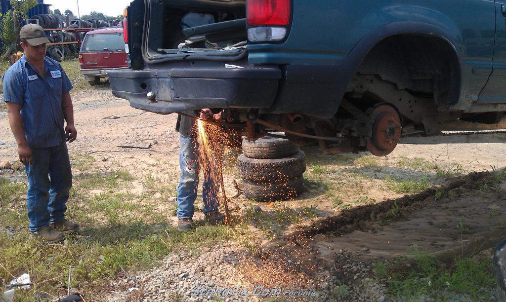
I went to a local pick and pull yard and got a good explorer 8.8 with 3.73's and a limited slip. It was hot / humid so why waste time. I burned it out.

166-270811125153-85271478.jpeg


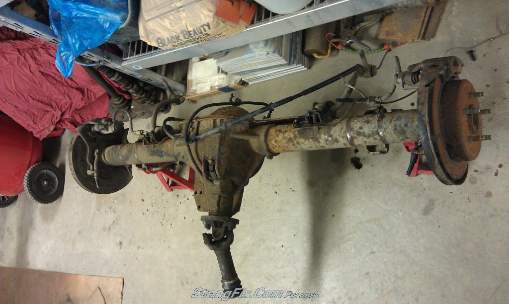
Once the rear was removed from the explorer, and unloaded into my garage, the real fun began. I set the complete rear end up on 3 jack stands. One positioned under each axle tube, and one was used to support the pinion.

166-270811125159-8530550.jpeg


This may not be the most correct way to strip it down to an empty housing, but it worked for me. I started with the intent of removing all the brake hardware. First was the brake hose lines that mount to the caliper. These hoses are held to the caliper by one banjo bolt each. They are removed with a 14mm Socket. Each hose is also bolted directly to the axle housing itself by one 10 mm bolt. Then two 10 mm bolts hold each caliper to the bracket. With the caliper bolts removed, the caliper lifts upwards and will be set aside to reuse. A 12 mm socket removes the parking brake & brake line bracket on top of the housing. The ABS sensor was then removed from the top of the housing with a 14 mm socket. Next I removed the parking brake clevis and spring mounted to the back of the dust shield. It was easily pried off with a large flat screw driver. Next came the rotors. Both of these rotors were held on by seized parking brake shoes. I removed the rubber plug and rotated the star adjuster to loosen. Once loose, the axles turned freely, and the rotor came off with the help of a rubber mallet. I then repeated the process for the other side.
 
Last edited by a moderator:
Re: Lethal289 Build thread

Four 14 mm bolts and nuts hold each caliper mounting bracket, and dust shield to the housing. Note for reassembly: The head of the bolt is towards the outside and the nut goes towards the rotor. Also the calipers mount towards the back topside of the housing.
The pinion flange is held on by four 12 mm 12 point bolts. I only have 3/8 drive 12 points so I used an adapter because I needed every bit of my 24 inch1/2 drive breaker bar to get them loose. I used a 2' piece of flat stock to keep the pinion from rotating. Once removed, the pinion flange will break free with the tap of a hammer.

Next I tackled the Explorer Sway Bar. I am unsure at this point if I will try to reuse it or not, so it is currently set aside for safe keeping. It was a pretty simple removal. Four 13 mm bolts hold it the back of the axle housing. Once removed, a pry bar helps break it free.
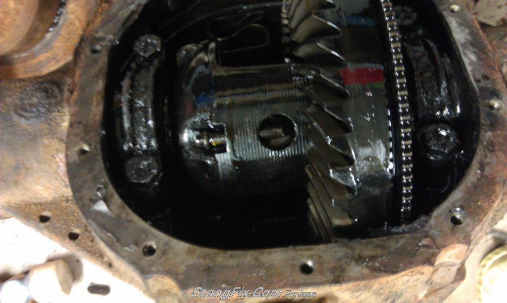
Now it was time for the dirty job. Ten bolts hold the differential cover to the back of the housing. Once removed using a 13 mm socket, the cover was stubborn to come off being held on by old sealant and gasket material. It was pried off with a screw driver. I turned the housing over, again supporting it by the pinion, and allowed most of the gear oil to drain out. An 8 mm bolt holds the differential centering pin in place. Once the pin is removed, I found that the c clips will slide right out.

166-270811125328-85501894.jpeg


166-270811125333-85512403.jpeg


Some Measurements that I took

With Rotors Installed, Wheel mounting flange to Wheel mounting flange: 59-5/8"

With axles removed: Extreme housing length: 56-5/16"

Long tube:
From differential Housing to backing plate side of axle flange - 20-1/4"
From axle flange to tube end - 23 - 1/16"
Stab depth - 3 -1/2"

Short tube:
From differential Housing to backing plate side of axle flange - 17 - 3/8"
From axle flange to tube end - 20 - 11/16"
Stab depth - 3.0"

Tube Outside Diameter: 3.225"

Tube Inside Diameter: 2.82"

With the Pinion set level:
Sway bar mounting plates are 7A* towards the top.


To be continued...
 
Last edited by a moderator:
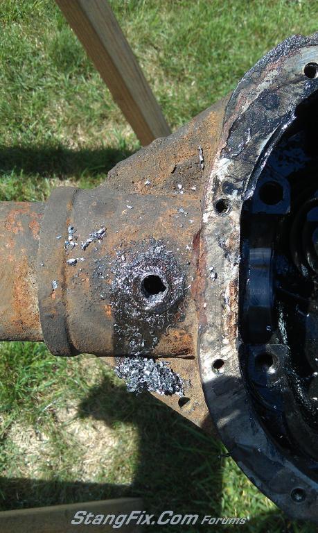
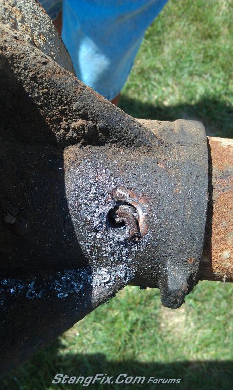
Now for the axle tube removal. Three spot welds on each tube need to be removed to free the tube from the housing. I started with a 1/8" drill bit and worked my way up to 1/2. This part is a little tricky because you have to guess where the center of the plug is. There are 3 holes that are cast into the center section. The center section is made from cast iron, and the tubes are steel. Steel drill bits do not like cast iron and will dull rapidly when they contact. I tried to drill up to 5/8 and ended up ruining the bit on the first hole.

166-270811125437-85671697.jpeg


Once the whole is drilled through the center of the plug weld, the remaining material can be driven into the axle tube with a small chisel or punch. I was really surprised how the weld just pops off of the cast iron with relative ease.

166-270811125442-85681123.jpeg


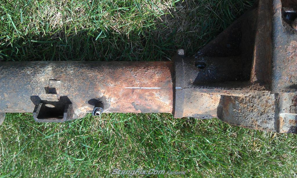
There are 3 welds on each tube so for me, this process needed to be repeated 6 times. Once the plugs were removed, i scored the housing and the tubes for a guide for reinsertion. I was able to line up a square on the housing and use it as a guide to scribe a straight line down the tube using a four inch grinder and cut off wheel.

166-270811125504-85732286.jpeg


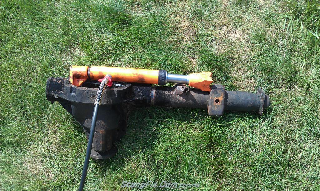
With the use of a hydraulic ram, the tubes come right out with ease.

166-270811125524-85761490.jpeg


166-270811125538-857714.jpeg


Hopefully in a few weeks, i will have another update.
 
Last edited by a moderator:
"RapidRabbit" said:
looks like a fun project. :part

I need to do something with my rear end too, eventually.
you might want to reword that before the perverts get a hold if it!
 
"SELLERSRODSHOP" said:
i noticed you pulled both tubes so assumed you are narrowing both sides? what are you planning for the axles?

ding ding ding... I was wondering how long until somebody noticed. Im planning on shortening two long tubes down to work with 31 spline fox body axles and retain the explorer disk brakes. That would make the rear end about 59.5" wheel mounting flange to wheel mounting flange and center the pinion. Perfect for a 67 stang.
 
"lethal289" said:
ding ding ding... I was wondering how long until somebody noticed. Im planning on shortening two long tubes down to work with 31 spline fox body axles and retain the explorer disk brakes. That would make the rear end about 59.5" wheel mounting flange to wheel mounting flange and center the pinion. Perfect for a 67 stang.

That's a cool way of doing it. I think I'll just use a short side axle and tube and eat the shorter width with offset.
Bill
 
"67 Fastback" said:
That's a cool way of doing it. I think I'll just use a short side axle and tube and eat the shorter width with offset.
Bill

You do realize you would need 1.5 inch spacer on each side just to run vintage wheels. If you want modern wheels you would need 2.5 inchs. Thats a little more than i would feel comfortable with.
 
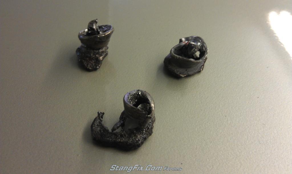
Here is a better shot of the plug welds once they are removed. I am still dumb founded how easily they separate from the cast iron. A chisel and less then 5 whacks from a hammer and they plop right out.

166-290811192727-8583419.jpeg


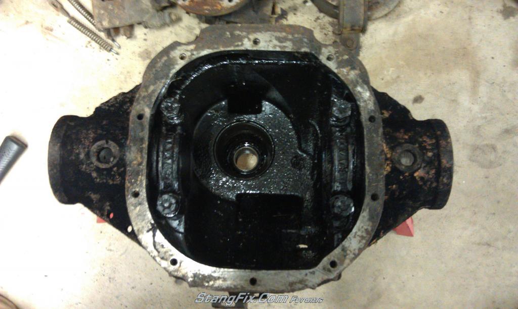
Here is the stripped housing the way it sits now. I just need to remove the front pinon bearings.

166-290811192722-8578527.jpeg
 
Last edited by a moderator:
Back
Top