Since the old hacked up wiring I removed isn't anything like these new harnesses I got, I'm confused. I printed out several diagrams but they don't seem to be much help since I don't exactly have a stock setup and my battery is in the trunk. THe pictures I took in the past of the wiring I had on isn't helping either, again because it was all fubar'd thanks to the PO.
First are these two red and blue ones coming from the firewall.
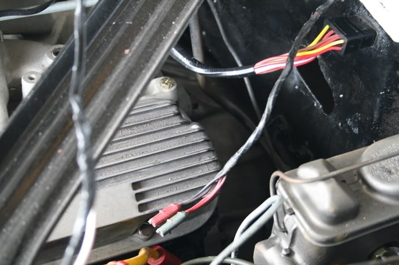
This part was cut off by PO so nothing to compare it to. I do know one of them goes to the oil sending unit (the white one with black wrapping?). Another to temp sending?
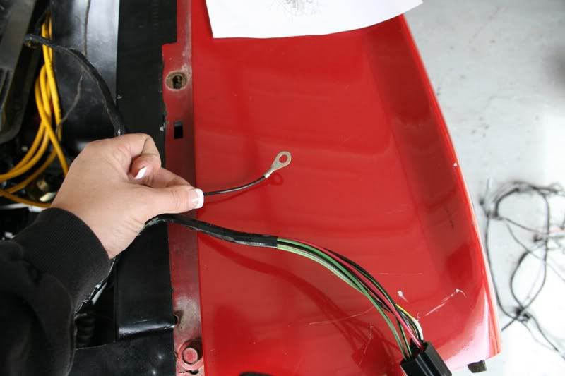
This is part of the headlight..I'm assuming the thin black is a ground (each side has one), but what do I connect it to? One of the little bolts on the apron?
From what I can tell, this is how these are suppose to connect to the solenoid. Yellow connects to the other harness. Brown? goes on the right side in the front and the red/blue goes in the front left. The big one with 2 wires on it goes on the left side.
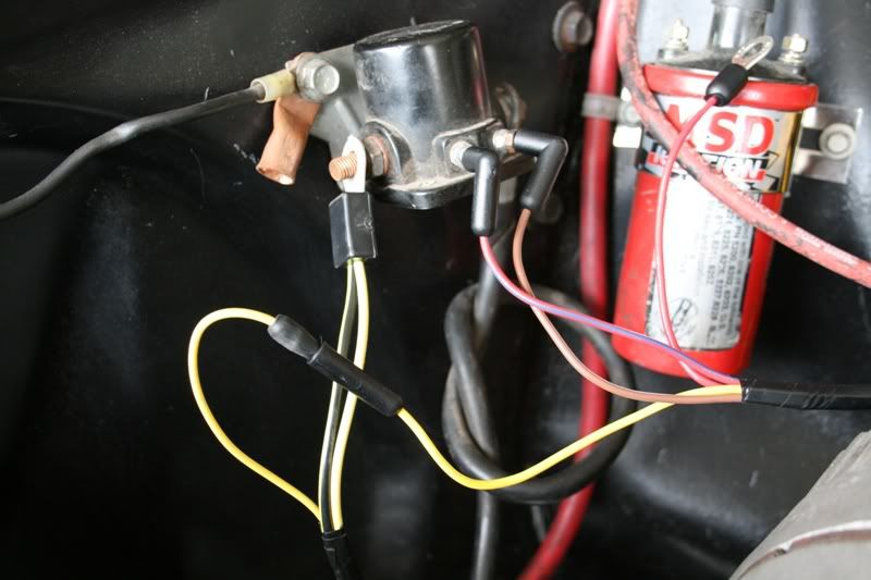
So what does this red one go to? Same side as the battery - left side?
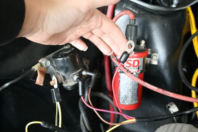
as you can tell the previous wiring was a cluster :censored and not really much help with multiple red wires. Yes my giant thick ground from the block to the apron needs replaced.
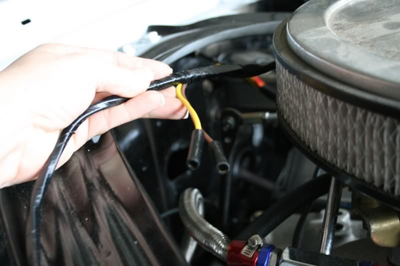
Yellow and brown.. can't seem to see anything those could connect to, unless they connect to something inside the firewall under the dash?
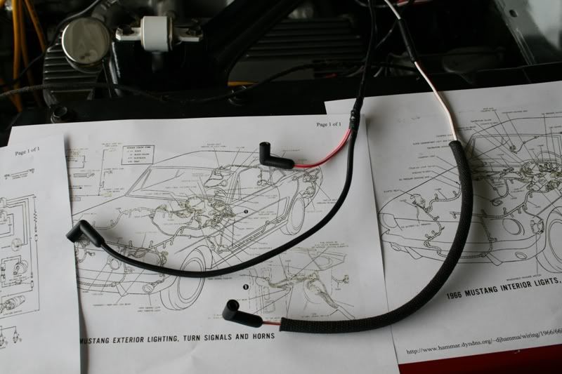
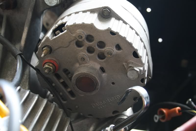
Alternator harness.. Mine didn't have one so this baffles me.
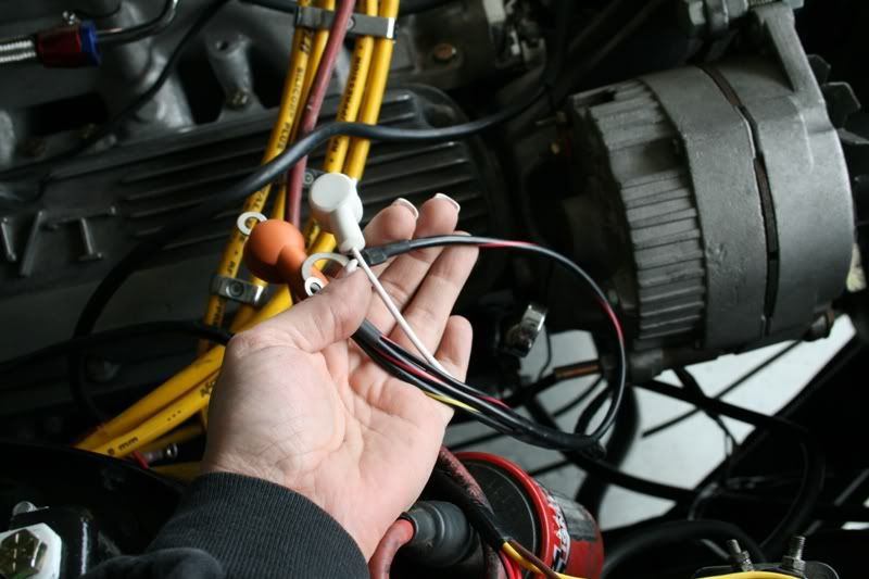
I know they go somewhere on the back!! :thu LOL
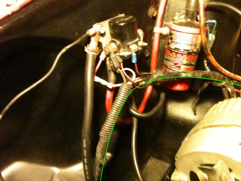
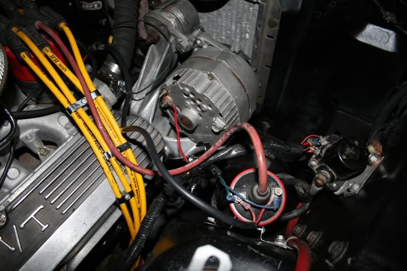
This was how it was connected by the PO. Again, not much help. :rant
..Off to go google some more and see if I can't figure this out. I'd like to get it all hooked up so I can start Gertrude up again and listen to her!
First are these two red and blue ones coming from the firewall.
This part was cut off by PO so nothing to compare it to. I do know one of them goes to the oil sending unit (the white one with black wrapping?). Another to temp sending?
This is part of the headlight..I'm assuming the thin black is a ground (each side has one), but what do I connect it to? One of the little bolts on the apron?
From what I can tell, this is how these are suppose to connect to the solenoid. Yellow connects to the other harness. Brown? goes on the right side in the front and the red/blue goes in the front left. The big one with 2 wires on it goes on the left side.
So what does this red one go to? Same side as the battery - left side?
as you can tell the previous wiring was a cluster :censored and not really much help with multiple red wires. Yes my giant thick ground from the block to the apron needs replaced.
Yellow and brown.. can't seem to see anything those could connect to, unless they connect to something inside the firewall under the dash?
Alternator harness.. Mine didn't have one so this baffles me.
I know they go somewhere on the back!! :thu LOL
This was how it was connected by the PO. Again, not much help. :rant
..Off to go google some more and see if I can't figure this out. I'd like to get it all hooked up so I can start Gertrude up again and listen to her!