• Hello there guest and Welcome to The #1 Classic Mustang forum!
    To gain full access you must Register. Registration is free and it takes only a few moments to complete.
    Already a member? Login here then!

My Custom Motor Mount build thread

I'll have to see if I can find those flange bolts locally. I do have an upper plate that helps with the clamping force, and had planned on using a washer on a standard Gr8 bolt. It appears only one of the brackets has 1/2" holes and apparently that was from a little too much grinding/filing of the hole to make it smooth. The other plate has the correct size holes. Oh well, no biggie!

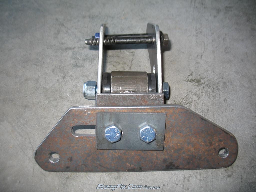
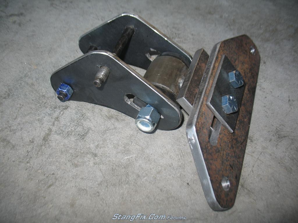
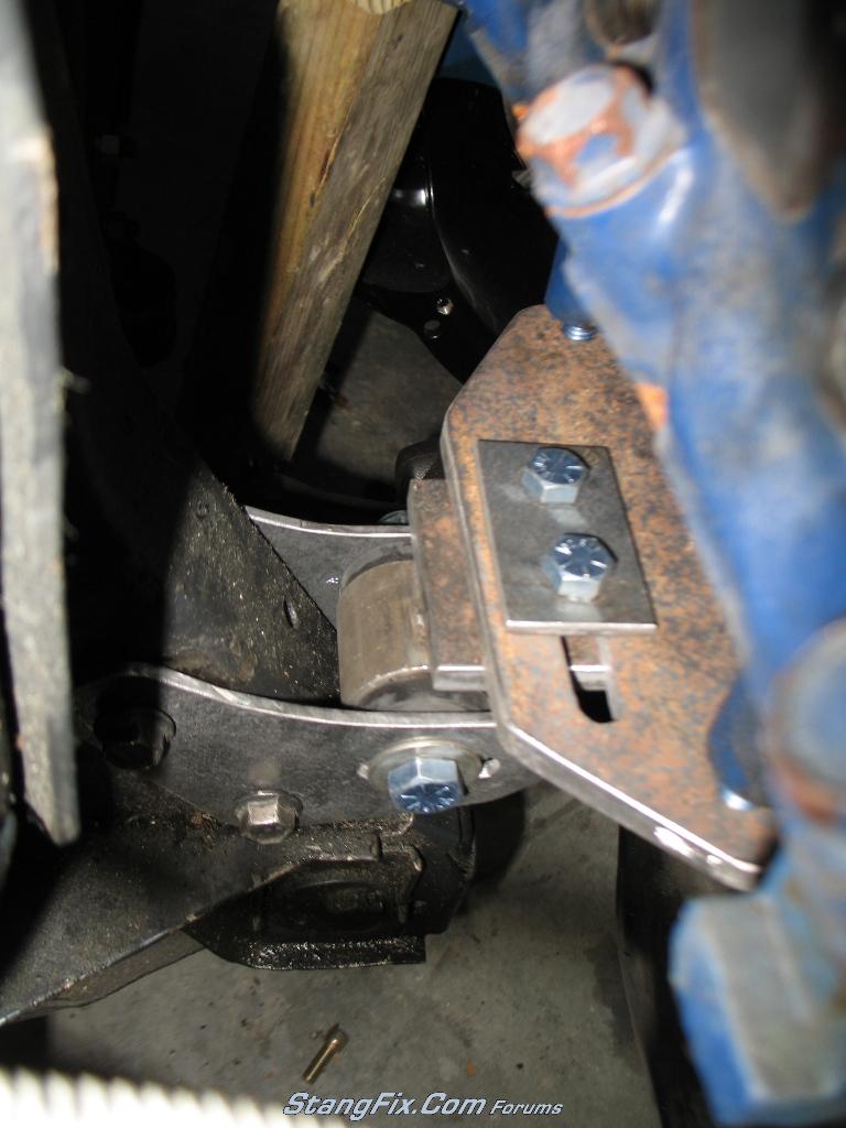
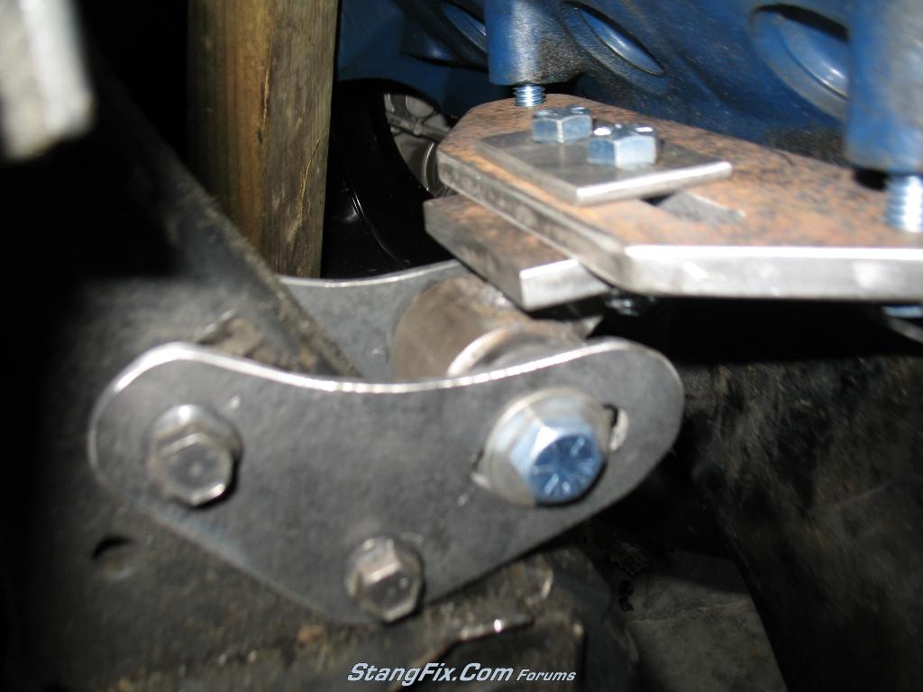
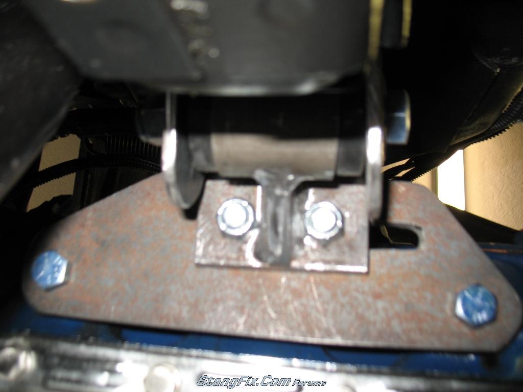
Below are some pictures of the raw assembly and then some of them installed. I did run into a slight issue in that with the motor at stock height and using my 1" lowering brackets w/o shims, I only have 1/2" clearance between the block and the top plate. This means that it'll only lower the motor 1/2" instead of the 1" that the brackets are supposed to allow. Somethings definitely screwy here! They were cut correctly (double checked) and measure out correctly in CAD, so I'll have to get out the old motor mount and double check my measured stock mount assembly heights :rp :rp :rp


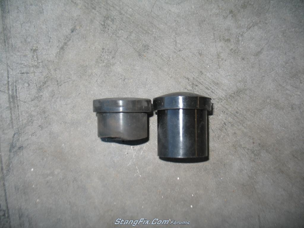
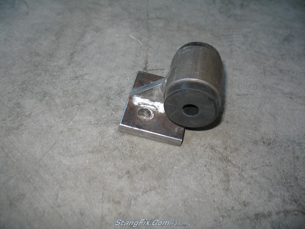
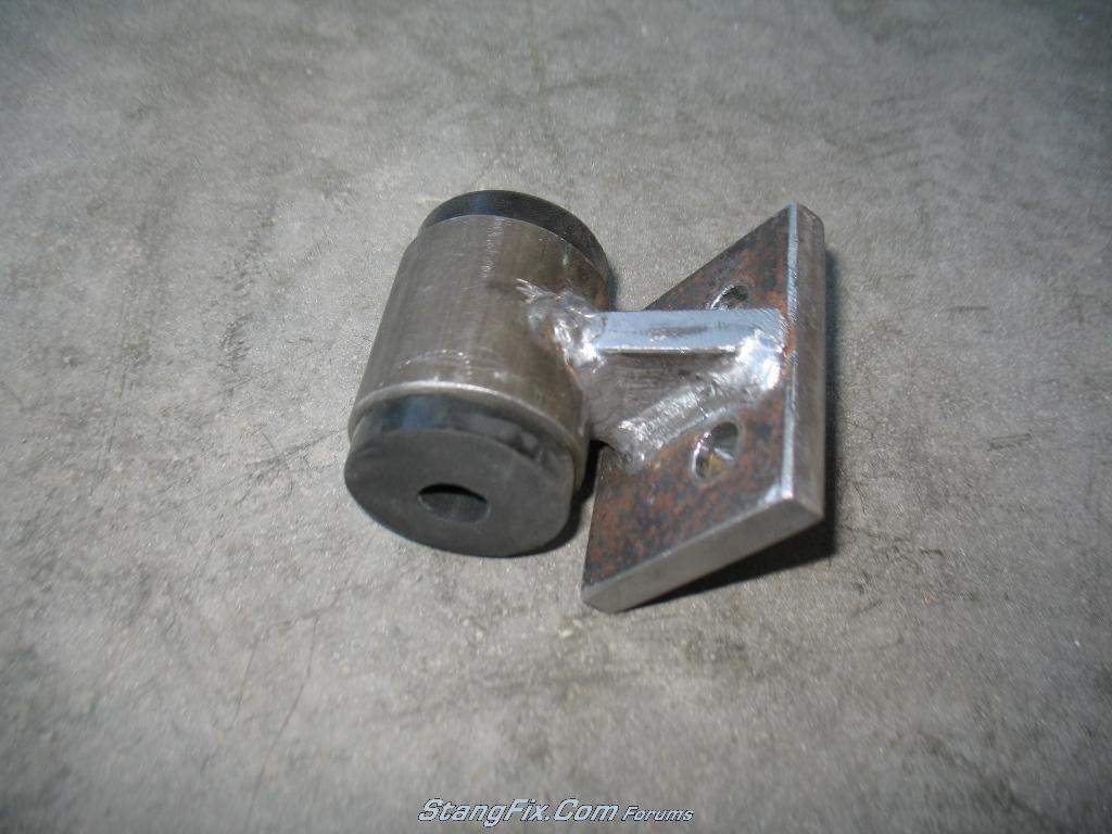
One of the pictures below shows the stock rubber leaf spring bushings next to the final version. I had to grind down the dome so that it is close to being flat, and then had to cut down the bushing length since the width of the steel tube is narrower than a standard leaf spring.

Another mistake that I made was that I forgot to include the weld width in my intermediate/Tplate, so I have very little clearance to the weld for the locknut. I plan on using nylok nuts, but there isn't room for any kind of washer there. I'll be changing the CAD files so that the holes are slightly further apart, so that others won't run into the same issue.

Tomorrow I hope to sandblast the parts and then get them painted. It might be till Friday before I get to install the mounts to see if these lower the engine enough to get my correct driveline angle. Considering this is my real first fabrication job and very very minimal metal cutting skillz/tools, it's turning out half a$$ decent with exception to the few hiccups. I'll update with more pictures once they are painted and the motor is actually sitting on them :5
231_04_05_10_6_44_00_0.JPG


231_04_05_10_6_44_01_1.JPG


231_04_05_10_6_44_01_2.JPG


231_04_05_10_6_44_01_3.JPG


231_04_05_10_6_44_02_4.JPG


231_04_05_10_6_45_51_0.JPG


231_04_05_10_6_45_51_1.JPG


231_04_05_10_6_45_51_2.JPG


231_04_05_10_6_45_51_3.JPG


231_04_05_10_6_45_52_4.JPG


231_04_05_10_6_46_39_0.JPG


231_04_05_10_6_46_39_1.JPG
 
Last edited by a moderator:
YOU CAN WELD THE 2 BOLTS STICK THROUGH THAT SQUARE PLATE THAT FUNCTIONS AS A WASHER BY THEIR HEADS.
SO YOU MOUNT THAT PART EASIER. IMO

BTW YOU ARE GOING A GREAT JOB .
 
You know you actually bring up a good point! I was considering doing the opposite and welding the bolt heads to the top clamping plate, so that you can drop the clamp plate and bolt assembly right into the holes at once. It also means you wouldn't have to get a wrench up top to hold the bolt head while you are tightening the nuts.

It seems easier to get to the nuts with a socket from the underside so welding the bolt heads to the top clamping plate would make tightening even easier. Doing the reverse would mean that you'd have to get a wrench up top and tighten it down, and with headers it gets to be a challenge to get a socket or wrench in there. I'll look into this further with the headers installed to see how much access I have. It's one thing to just have to stick a wrench up there to hold the bolt head in place while you tighten the nut below, but to have to rotate the wrench or socket up top requires much more room.
 
You've got a point there , but the future will decide whats easier.
I don't want to brake down your fantastic job , I only want to give some suggestions to consider.
4 eyes sees more then 2 eyes I always think.
B.
 
Oh I appreciate any kind of feedback on these! The more the better IMO, regardless if it's good or bad. :)
 
Welding the bolts to the small plate is a great idea. It is a real pain in the arse to tighten those bolts on my RM mounts.

The motor mounts look great! Keep up the good work and keep us posted on your progress.
 
If you are open to suggestions/opinions I will add one. I would think you could use two triangular pieces, spaced slightly apart, instead of the single one you have currently to connect the bushing cylinder to the mounting assembly. It seems there would be enough room to do this.
This would greatly reduce the chance of fatigue failure in this area. The two pieces would prevent any twisting of this joint caused by motor torque.
 
"Horseplay" said:
If you are open to suggestions/opinions I will add one. I would think you could use two triangular pieces, spaced slightly apart, instead of the single one you have currently to connect the bushing cylinder to the mounting assembly. It seems there would be enough room to do this.
This would greatly reduce the chance of fatigue failure in this area. The two pieces would prevent any twisting of this joint caused by motor torque.

Thanks for the tip! I mentioned trying to do this earlier in this build thread but ran into clearance issues with the bolts. If you look at the 5th picture from the top in my previous post, imagine putting two triangular pieces towards the outer edge of the bushing cylinder. Then figure out where to put the bolts. There definitely wouldn't be room between the two pieces, so this would push the two bolts further apart. You then run into issues with the shock tower brackets interfering with trying to tighten the nuts. The only solution would be to push the bolts further out past the tower brackets. This would create longer top plates or longer slotted holes, but not really a huge issue IMO. This is definitely an option for those that want to build there own. Appreciate the feedback.
 
looking good. the weld the bolt idea is nifty. Are you considering making this part out of aluminum or could it be? What does it weigh?

Have you had a structural engr do some analysis on the loads and if you're in good shape in that department? You also might want to weld a washer on on the plate where the two nuts go near that fillet/gusset area (the piece in the middle). Weld beads might be what the nuts will end up riding on and that will provide a point stress load on them.....
 
Looking at it again I can see where it would get pretty tight. Another way to accomplish the same (maybe even better) support would be to put a "T" off the triangular piece, tying the cylinder to the same plate in a different plane. In pic #8 of your recent post, this new piece would be vertical and perpendicular to the existing triangle. It would weld to the cylinder, vertical end of the triangle and the same plate as the triangle piece. Essentially between the tower plates.

Too confusing? or do you see what I mean? This would negate any forces either twisting or pushing against the side of the triangle piece.
 
"Horseplay" said:
Looking at it again I can see where it would get pretty tight. Another way to accomplish the same (maybe even better) support would be to put a "T" off the triangular piece, tying the cylinder to the same plate in a different plane. In pic #8 of your recent post, this new piece would be vertical and perpendicular to the existing triangle. It would weld to the cylinder, vertical end of the triangle and the same plate as the triangle piece. Essentially between the tower plates.

Too confusing? or do you see what I mean? This would negate any forces either twisting or pushing against the side of the triangle piece.

I see what you mean and Sluggo mentioned that previously. Basically using a gusset plate to stiffen that section up. The only catch is that the clearance between the top plate of the T and the cylinder at this location is about 1/4", so the gusset would basically be one big weld by the time you weld the top and bottom. I may still look into fitting something in there to stiffen things up if I find fatigue is an issue with these mounts after some use. Thanks for the tip!
 
"opentrackerSteve" said:
looking good. the weld the bolt idea is nifty. Are you considering making this part out of aluminum or could it be? What does it weigh?

Have you had a structural engr do some analysis on the loads and if you're in good shape in that department? You also might want to weld a washer on on the plate where the two nuts go near that fillet/gusset area (the piece in the middle). Weld beads might be what the nuts will end up riding on and that will provide a point stress load on them.....

Thanks! Haven't thought about using aluminum but doubt it'd be strong enough. Haven't weighed them yet but they are a bit heavier than the stock units. I probably overdid it on some of the steel thickness though.


I am a licensed structural engineer. Determining what kind of load these things will see (since dynamics are involved and multiple possible load directions) has been my sticking point. Probably more geared towards a Mechanical Engineer design than structural. I can't quantify what kind of front to back (in relation to the engine) force these things will see in order to determine if that gusset is even worth considering. Then trying to estimate the downward force from the engine due to not only the dead load but the torque is another thing I'm not sure on.

The welds are just far enough away that the nuts don't touch the welds, but welding a washer would be a good idea!
 
"buening" said:
I see what you mean and Sluggo mentioned that previously. Basically using a gusset plate to stiffen that section up. The only catch is that the clearance between the top plate of the T and the cylinder at this location is about 1/4", so the gusset would basically be one big weld by the time you weld the top and bottom. I may still look into fitting something in there to stiffen things up if I find fatigue is an issue with these mounts after some use. Thanks for the tip!

Even so, adding a connection in a second plane like that would give it considerably more strength. Nice work by the way.
 
Nice..What did you end up paying for the steel and the work to cut it??

Would like to get a set..

"buening" said:
Nothing too exciting since they are bare steel and still need cleaned up. I did check for waterjet pricing in my area and only found two places that have the capability. One wanted $150 and the other wanted $225. My mounts may not look as pretty as one from a waterjet, but paying those prices would not have saved me a dime.

These pics are for one motor mount only. The other set looks identical obviously. The lower right and lower left pieces are 3/8" as well as the triangular piece, while the rest is 3/16". The lower right plate probably weighs about 5lbs by itself....definitely bulky! I only had time to make a single 3/16" shim for each side. If more shims are needed I will make them. The shim is to the right of the lower left 3/8" piece and didn't come out exactly like the 3/8", so I'll take a grinder to get them closer to the same size.

I just need to get out the die grinder and get to work cleaning up these edges! Will report back whenever I get the tubing and everything welded and edges all cleaned up.
 
Buening- nice work. One thing I don't think I saw mentioned is that you can only go so low with the mounts before your steering arms contact the oil pan. I did some mocking up in this area when I wanted a better angle for my TKO.

And coupe3W, more pictures please. Those flares look fantastic! Details...
 
I apologize for the lack of updates. I spent the entire weekend snapping pics while I'm mocking up the T56 but haven't had much computer time. I did have to make a new top motor mount plate for the drivers side. Needless to say my measurements and cardboard mockup was limited to the passenger side, only to find out that the motor mounts are offset 1.25". They are offset so that the factory top motor mounts can be used on either side. I'll post up some pics and updated cad drawings soon.

Ken, yes there is definitely a max that you can drop the motor. I'll have to take a measurement to see exactly how much these lowered the motor but they should be exactly 1". I just installed the headers and the steering linkage and I have roughly 1/4" or so between the oil pan and the steering linkage. Thankfully no clearance issues! I will have to make a new front crossmember due to the fact that I lowered the motor and moved the motor back. Due to clearance issues with the heater core tube on an A/C car (behind the passenger head) as well as power steering pump line nearly touching the shock tower I was limited to moving the engine back 1.25" instead of the planned 1.5". I could fabricate my own PS hard line so that it routes in a different direction that would give me extra clearance but I'd still be stuck with the heater core tube. I bent it slightly so that I could attach the heater hose. I'll put all this info and pictures if and whenever I start the T56 conversion thread :scar
 
I am following up this topic with great intrest.You're doing a fantastic job. :coo :coo :coo
 
Well I finally got time to take the mounts out of the car and get them painted up. Below are pics of the final assembly. For those that want the CAD file or the PDF to print out for a cut-sheet, send me a PM or reply to the thread and I'll send it to you. A few things I learned from this process is that moving the engine back 1" is about the safe maximum before you get into clearance issues, not only with the motor mounts but other things like heater core tubes or PS lines. I went with 1.25" but it required modifications to the mounts and the previous two items. Also, dropping the motor 1" is the max you can go with these mounts without issues with the bushing housing and the shock towers, as well as steering drag link clearance issues with the oil pan. They are still really close and may find that I have vibration/clattering issues with the motor running. If I have problems I'll report back.

231_13_06_10_4_05_53_0.JPG


231_13_06_10_4_05_54_1.JPG


231_13_06_10_4_05_54_2.JPG


231_13_06_10_4_05_54_3.JPG


There are some washers missing in the pic that were installed later. FYI
 
Last edited by a moderator:
Back
Top