• Hello there guest and Welcome to The #1 Classic Mustang forum!
    To gain full access you must Register. Registration is free and it takes only a few moments to complete.
    Already a member? Login here then!

70_Fastback: RAT ROD - 193x Ford / 1942 GMC Truck

"AzPete" said:
Your skills could provide a very nice "card" for the wife......just need to land them in the right business. You have the design and build capabilities that are rare.

Outstanding.....

I know.., I am still searching for that right opportunity.
 
"Mach1ne" said:
Keep it up and you are going to need that big diesel engine I just gave away to power the thing.

So you don't have to build your own starter button, I found one on-line for you.

image.php

Cup%20Shut%20The%20Hell%20Up.gif
 
Last edited by a moderator:
My Dad had skills like that. He was THE Research and Development department for a place in Sioux City Iowa called American Equipment Corp. back in the 60's and 70's. The company would tell him the piece of farm equipment they wanted.....he built it from scratch with no designs, field test it to tear it up, rebuild it better. Once ok'd by the company and they blueprinted it, he built the jigs for it to go into production. He designed and built most of the Cherokee Equipment that was used throughout the country.

Later in life, we built accessories for the Honda Helix 250cc touring scooters plus custom accessories for local motorcyclists. Had a lot of fun. I learned a lot from him............
 
and to think, not only do I KNOW the guy, but he has my sweatshirt too.
 
"silverblueBP" said:
and to think, not only do I KNOW the guy, but he has my sweatshirt too.

LMFAO!

Actually it's Bonnies now. She's been wearing it. Because it's small and all... :nut
 
Nice work, Jeremy, but I do have one concern. The rotating mechanism that alters the fore-aft direction to the sideways direction into the Master Cylinder. My first reaction was OMG...that's going to put a side load onto the MC because the rod will not always be perpendicular to the MC. The video showed that the amount of offset was smaller than I anticipated, but still...I believe you would be better off keeping the rod into the MC straight (perhaps by a separate through-hole to keep it perfectly aligned) and having the plate push against the rod.
 
The bellcrank by design shouldn't be an issue since our regular brake pedals swing on an arc too... The belcrank, looks a little short thus not keeping the stroke more linear... I think one thing to try first is shorten the rod coming from the pedal, and lengthen the rod going to the M/C... If you have an even amount of travel on either side of center... then the stroke ratio will be more evenly split. The way it is now, the pedal to M/C ratio will increase... As you continue to press the pedal, you will incrementally have less M/C travel. It starts at 1:1 and ends at something like 1.25:1 (assumption on the actual ratio) ... I hope that makes sense.

If you could set it such that at the midpoint the bell crank arm is at a right angle to the M/C rod, then I think that would be the best geometry for what you currently have... Lengthening the lever arms on the bellcrank would help too...
 
"stangg" said:
The bellcrank by design shouldn't be an issue since our regular brake pedals swing on an arc too... The belcrank, looks a little short thus not keeping the stroke more linear... I think one thing to try first is shorten the rod coming from the pedal, and lengthen the rod going to the M/C... If you have an even amount of travel on either side of center... then the stroke ratio will be more evenly split. The way it is now, the pedal to M/C ratio will increase... As you continue to press the pedal, you will incrementally have less M/C travel. It starts at 1:1 and ends at something like 1.25:1 (assumption on the actual ratio) ... I hope that makes sense.

If you could set it such that at the midpoint the bell crank arm is at a right angle to the M/C rod, then I think that would be the best geometry for what you currently have... Lengthening the lever arms on the bellcrank would help too...

That is exactly what I planned to do earlier when I mentioned re-adjusting the heims to reclock the bell crank! Scary huh...? :confu


And @ Mid - the MC rod is a fixed rod (it is retained inside via a snap ring) it swivels & pivots inside the cylinder bore very freely to begin with. But yes, I concur the movement should still be minimized to the maximum extent.

Thanks guys!

Next up: cowl steering... (this should be fun)
 
"70_Fastback" said:
That is exactly what I planned to do earlier when I mentioned re-adjusting the heims to reclock the bell crank! Scary huh...? :confu

Oops with all those pretty pictures I missed that comment under the video link...
 
Just doing my monthly check-in. It's looking great!! If you get it done by May, I'll trailer the Studebaker up to your place--don't want you to run out of projects!
 
Cowl Steering

Got the cowl steering made and installed this weekend. I am just waiting on my steering coupler to show up so I can finish the steering column & get the steering wheel on there.

Nothing like trying to fit 10 lbs. of :censored into a 5 lb. bag....

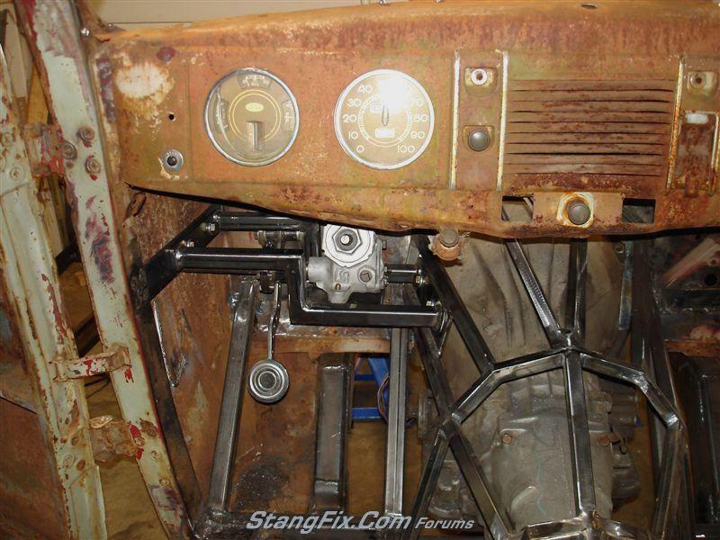
I messed around with where I wanted to locate the steering box under the dash. Once that was determined I stated making the mount for the reversed Corvair steering box.

Started by making the base mount for the steering box:
26-070211093749-73852161.jpeg


The base of the steering box, for some reason, is not parallel with the output shaft of the steering box. So the base had to be angled to set the shaft angle straight.
26-070211093752-73861639.jpeg


Welded on some mounting flanges. The mating surface inside the cab has welded captive nuts for easy install & removal:
26-070211093754-73872254.jpeg


Finished mounting plate for the steering gear box:
26-070211093757-7388729.jpeg


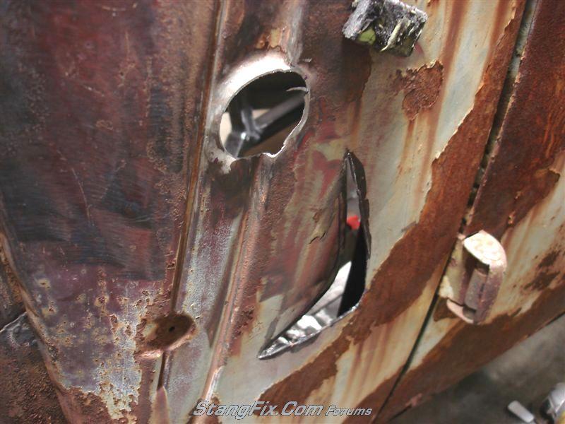
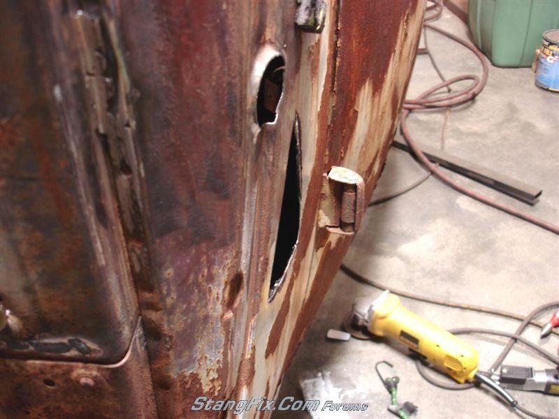
Next was drilling the side of the cowl for the out put shaft extension & support bearing. I should have planned a bit better because the shaft came through in a horrible spot!
26-070211093758-7389911.jpeg


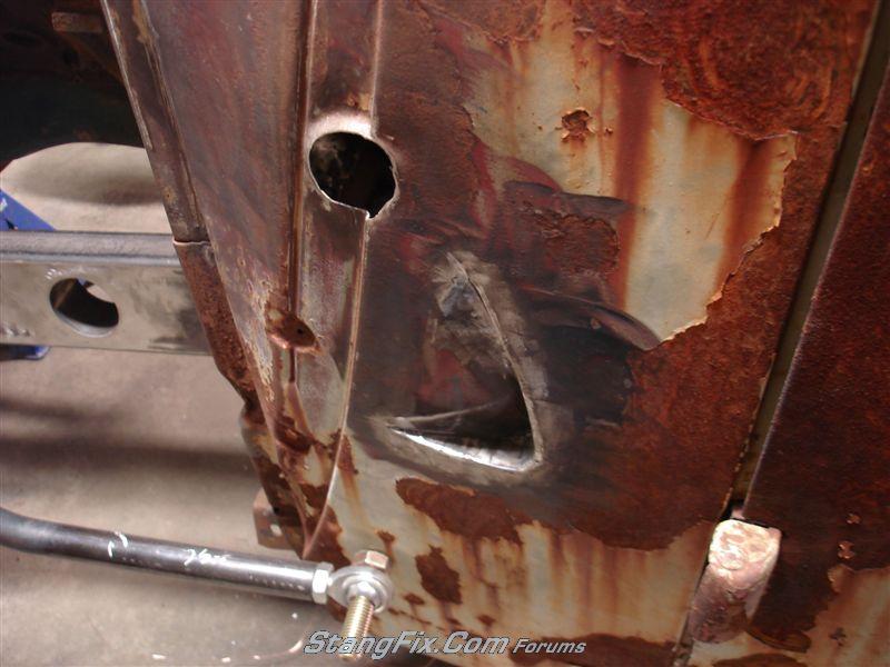
I had to flange a lip on the top to sit flush against the alignment bearing that will go in that hole. Also, below, I cut in a crescent shape to make a pocke recess to accomodate for the rearward articulation of the pitman arm.

Depth of the pocket inset:
26-070211093800-73902494.jpeg


New metal welded in to close in & formt he pocket:
26-070211093803-7391297.jpeg


26-070211093806-73921428.jpeg


Jump ahead....

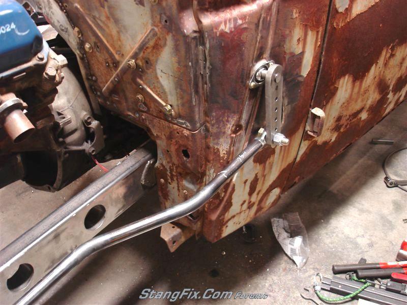
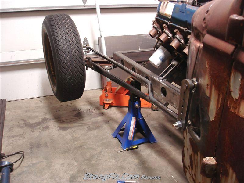
Home made pitman arm & extension shaft installed through the cowl mounted alignment support bearing. The pitman arm is pinned though the shaft, welded & solidly welded on the backside:
26-070211093810-7393427.jpeg


26-070211093816-73951286.jpeg


I had to heat & jog the drag link to help clear the tire on a sharp left turn:
26-070211093813-73941720.jpeg


26-070211093818-7396703.jpeg


Now back up a bit to the steering box. Since the box is inside, under the dash I couldn't use the stock pitman arm because I had to extend it outward. I had to way to spline a shaft internally so I had to buy a pitman arm, cut off the large end, turn it down and press it into a tube. Since it's forged steel I had to put the torch to it and heat it prior to welding it all together. The end result was a coupler that goes onto the steering box output shaft and then the extension shaft welds to the other half and the 2 pieces bolt together. This was a pre-finished pic of the adapter:
26-070211093746-73801258.jpeg


And now an under dash shot, bracket fully bolted in:
26-070211093822-73971183.jpeg


This shot makes the input steering shaft look way off, but it is centred between the 2 guages. The steering column housing tube will cut into the bottom of portion of the dash and be welded in for support.
26-070211093824-739869.jpeg
 
With all that steel, you better be looking at more power.....

Nice work. Could you have run the drag link on the outside of the pitman arm and avoided the cresent cut?
 
I tried it that way, but believe it or not but it interfered with the tire on a hard left hand turn. It's close to rubbing as it is now. But it clears.
 
"70_Fastback" said:
I tried it that way, but believe it or not but it interfered with the tire on a hard left hand turn. It's close to rubbing as it is now. But it clears.

That could have been solved with move bend where you already did the offset. Don't get me wrong.......just curious.....always learning about things.
 
True. But I also didn't like the look of the connection on the outside of the pitman arm. It looked out of place.
 
I can understand that....gotta have the right "look" or your time is wasted. You need to throw some water on all that new steel to get the patina to match.
 
Back
Top