apollard
Active Member
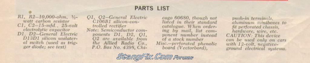
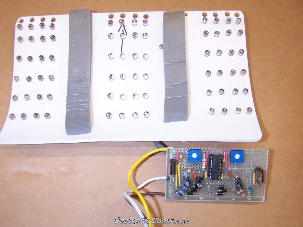
"tarafied1" said:thanks for the help guys, I too have no idea what your saying! I found this article that I kinda understand (it's old). Does it help?
Hmmm. Never thought about using SCRs; slick little circuit. Could probably use MOSFETs the same way. I'll have to look into it.
Any bigger files? I printed these, but they are hard to read from the d/l off the gallery. I can't read the designation of D1 & D2. It looks like D13D1 on my print, but I can't find that in any part cross reference. I think they are a zener diode, but not sure.
EDIT: OK, I think D1/D2 might be DIACs. Although, there are very few that operate in the 12V or less range. If you can tell me the GE # on those, it might help.