Given my somewhat long winded and overly detailed writing style, this is probably going to be a two post night...anyway on to the fun!
Over the holidays I spent a pretty significant amount of time in the shop with the focus being on the EPAS and column install. I have a Toyota Prius EPAS motor that will be used for the install. I've seen many threads where people mount them, essentially, upside down with the motor end up towards the wiper motor...sometimes clocking the wiper motor 90 degrees to get a the EPAS tucked up a bit more. Then I found a thread where a fella mounted with the orientation towards the top which, more or less, hides the motor. So this is what I set about to replicate.
First thing, I removed the pedal support and attempted to mock up the EPAS. The EPAS has a 1.5" tube surrounding the shaft...which i promptly cut off so i could get more bite on the shaft...otherwise I believe the column would have been too long. In the process, i discovered theres a bearing at the base of the tube...so dont cut into that. After cutting the tube down, I tacked a piece of the original mustang column to the steel collar on the EPAS and set about mocking it up to the pedal support. This was extraordinarily difficult to do on my own but I managed. After it was all said and done, i discovered that the angle wasnt "right" and I ended up taking too much out of the pedal support. Grand scheme...small error that I'm actually okay with. I dont think the structural integrity of the pedal support is compromised in any way...even if it was, this isnt a structural part of the car. I might use the extra opening for wire routing.
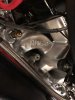
Anyway, as said, in order to get the motor oriented on top, i had to cut out a little bit on both sides to allow clearance for the motor.
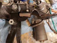
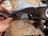
The lower shaft assembly was cake. It's a 3/4" shaft that I cut to length and welded to a coupler.
https://www.summitracing.com/parts/brg-312500
As a safety measure, I rosette welded as well as added a 1/4" steel rod cross drilled through the coupler and shaft. That way, if the welds let go, the shaft will catch it.
Picture prior to adding the cross plug
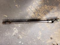
I used the original column cut to length and welded to a flange that I made that will bolt to the lower part of the unit.
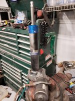
The assembly:
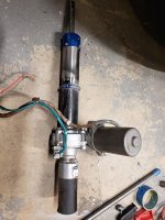
Now was the kind of unnerving part...cutting up the Ididit column...mostly because they are pretty expensive units and I legit did not have any idea how this was going to work. I was pleasantly surprised to find that the Ididit columns use a DD shaft for the top 20" or so from the top of the unit! I swagged a cut about halfway through the tube to discover they use two pins to attach whatever bottom shaft is ordered. My guess is so they can mass produce the top parts and easily set the lower for whatever is ordered. Whatever their reasoning it worked out GREAT since I had already ordered a DD coupler planning on "machining" a DD shaft out of both the input shaft of the EPAS and the column shaft.
Much more confident in my plan, I set about trying to figure out a length for the column. This was super scientific...i sat in the drivers seat with the tape measure and the wheel and held it to where it felt comfortable and cleared stuff. I determined 14 3/4" from the wheel adapter to the top of the EPAS was the ticket for me. I checked this about 30 times before cutting down the Ididit column.
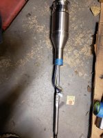
^ you can see the lower pinned shaft. I used these pins as my safety pins in the shaft
I then cut down the EPAS input shaft exposing 3/4" above that tube mentioned earlier. I ground this down into a DD. Inserted my DD coupler and checked runout. Best I could get was .01" so I went with it. I welded the coupler to the EPAS and safety pinned it.
DD on the input of the EPAS:
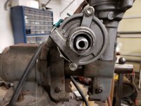
Rosette welds...this was taken prior to pinning:
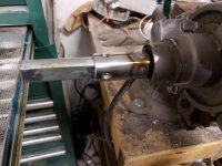
I'm very comfortable this will never come out given the downward pressure from the upper column.
The tube over the shaft of the Ididit column made it impossible to cut it to length so I cut the tube back about 2". There was a lot of measuring here. So, when I did all my baseline measuring i did it to the top of the torque sensor. There's about 1/4" between the top of the sensor and the base of the shaft with another 1/2" up to where I cut the tube...adding the 3/4" of the coupler, I cut back the shaft about 1 1/2" (actually about 1 5/8"). Welded the tube section I'd cut off to get at the shaft, smoothed, painted.
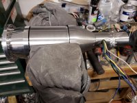
I didnt get a picture of the completed unit like a fool...but here's it installed in the car:
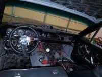
Sad news...the control box appears to be dead. I'm pretty sure I messed it up experimenting with it. I'll order a replacement and test again. Regardless, steering turns flawlessly! Overall, I'm very happy with how this panned out. More to come in the next post.