• Hello there guest and Welcome to The #1 Classic Mustang forum!
    To gain full access you must Register. Registration is free and it takes only a few moments to complete.
    Already a member? Login here then!

1952 F1: The Garage Roommate

Select from the following six options, derived from two basic designs w/ colors and options.

  • A

    Votes: 1 7.7%
  • B

    Votes: 7 53.8%
  • C

    Votes: 2 15.4%
  • D

    Votes: 0 0.0%
  • E

    Votes: 3 23.1%
  • F

    Votes: 0 0.0%

  • Total voters
    13
  • Poll closed .
A variable DC drive for the bead roller.
And we have a correct answer!

In truth, much more than just the drive control. Aside from the two shafts and spur gears, everything else has either been heavily modified or fabricated from scratch. I have plans to make quite a lot with this thing so worth the effort upfront to make it a viable tool.
 
So let's wrap up the bead roller project so we can get back to the truck!

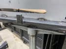
Quick summary. I bought one of the typical Chinese bead rollers. Got the Woodward Fab version. Seemed the best of lot. 1/2" steel. Solid as they come out of the box. Price shot up on these due to supply issues. A year or so ago they were under $150. I had to pay $185. Unboxed it and took apart. Despite the thickness of the steel used they still flex too much. The top arm drives out of line with the lower resulting in skewed and misaligned forming wheels. 1001 videos on Youtube of guys doing their own thing to reinforce it and fix the problem. I went at it with 1/2" x 2" steel plate. Nothing tricky about it other than where you weld it on. I had kind of a master plan in mind which included a work table so placement of the reinforcement pieces was critical to facilitate its mounting. I mounted sections of the 2" steel perpendicular to the upper frame leg to eliminate the chance of flex-movement. Also cut up pieces of the same 1/2" x 2" which I drilled and tapped to be welded on as mounting tabs for the work table.

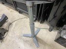
The bead roller also requires a stand (clamping in a bench vise as claimed possible is simply not a viable option) and instead of making one from scratch I splurged a bit and bought a very heavy duty piece designed to be a support stand for industrial use. Rated at 1700 lbs. What I liked about it was the VERY heavy cast base and on the upper end another cast piece that mounted a large, hefty roller. I cut off the two "ears" that housed the roller shaft ends to make a flat surface onto which I rested and then welded the bead roller frame. Using it this way, aside from serving as an adjustable height stand, also functioned to act as a lateral support for the lower leg of the bead roller frame to prevent movement.

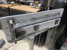
For the drive motor I went cheap and available and bought a winch set-up from Harbor Freight. Saw a video on Youtube of a guy who used one and figured for $70 I'd give it a shot. This is why I had to make the custom DC drive control. Get the power down to 12VDC to power the winch motor. The real challenge came about when mounting the motor to couple to the roller shaft. The winch motor drives an output shaft through a planetary gear arrangement. The output shaft is simply a strange star pattern shaft melded into a spool roller that takes up the winch cable. I sawed that off and ended up with about an inch long section of that "star" shaft. I welded a 3/4" shaft collar to the end that shaft and a short section of keyed 3/4" round shaft out the other end of the collar which now served as a fixed coupling of sorts. Note that getting all those components EXACTLY centered when welding together is critical. After that all I needed to do was source some sort of coupling to marry the 3/4" output shaft to the 25mm bead roller shaft. Found what I wanted in a flexible "spider" coupling and problem solved.

Last challenge was to make a bracket to mount the drive assembly to the bead roller framework which would align the two couplings (drive/driven). Turned out that a simple flat plate against the existing roller frame was almost right on. Just needed a small shim between the two to get the shaft alignment square.

Last thing to do was build the work table. When working with large, flat pieces of metal having a surface to rest it against as it drives through the roller is very helpful. Eastwood sells one I could have adapted but at something in the range of $135 plus shipping I figured I'd be better off making my own as I wanted it and for much less. Used some 3/4" square tubing for the framework with a piece of 16 ga steel for the top. I included in the design a couple pieces of round tubing that ran from the front edge back into the roller about 12". I also left the ends of a couple of the 3/4" square tubing open at the front edge as well. These will serve to mount a table extension (as needed) as well as any accessories I might desire. Think guides or hold downs/ups. When bead rolling consistent entry and positioning of the workpiece is key to a quality finish so I am incorporating every trick/aid I can think of in the design. I still need to finish up an inner guide fence but that is for another day!

Oh, and I painted it all other than the table surface. It'll get phosphoric acid treated and be good to go.

I know that was long winded but if anyone is really interested in the how and why I figured I should share. For the others...PICS!

frame1.jpgframe2.jpgstand.jpg
 
coupling2.jpgfinaldrive2.jpg

tableinstalled.jpg

The table mount was designed to allow it to drop down in front to either swing out of the way when not needed or to make changing the dies easier. The frame extension in the back acts as a stop against the upper arm support.
droptable1.jpgdroptable2.jpg
 
Oh, I forgot to include that the roller is operated via a foot pedal. I repurposed the one that came with my TIG welder that functions great as a simple on/off trigger but was worthless for it's originally intended function.
 
Very nice, nothing like having to fully rebuild a new piece of equipment! Is the DC drive variable, or just and off and on with the foot pedal? I am not familiar with power driven bead rollers, so I don't know if variable speed would be a nice addition or not needed.
 
Very nice, nothing like having to fully rebuild a new piece of equipment! Is the DC drive variable, or just and off and on with the foot pedal? I am not familiar with power driven bead rollers, so I don't know if variable speed would be a nice addition or not needed.
Absolutely it is (and needs to be variable). If you're just running some long straight line and using a guide you can move along fairly quickly. If trying to follow a curve or doing something more intricate its better to be able to creep along. I built my motor control to be variable via a pot on the machine and the pedal simply switches the DC output to the motor via a 20 amp solid state relay (like you would use for the headlights in your car).

It wasn't a cheap project by any stretch but I ended up with a machine that is structurally as good or better than units priced at over $1000 (looking at you Eastwood) and capable of doing everything I should need. For about half the cost.
Would it not make sense to make it variable via the pedal, as to keep your hands free?
 
Would it not make sense to make it variable via the pedal, as to keep your hands free?
Not really. It's not like your TIG welding where you may need to raise and lower your power level depending on other variables as you go along. I suppose you could use it if you are making a turn then into a long straight run kind of situation but you're just forming metal. It doesn't care how fast you go. It's not a race. Better to approach it like a tortoise. Smooth and steady. The better you get at it the faster you might want to go but in my case it's not like I'm in production on parts to make and sell or anything.
 
Not really. It's not like your TIG welding where you may need to raise and lower your power level depending on other variables as you go along. I suppose you could use it if you are making a turn then into a long straight run kind of situation but you're just forming metal. It doesn't care how fast you go. It's not a race. Better to approach it like a tortoise. Smooth and steady. The better you get at it the faster you might want to go but in my case it's not like I'm in production on parts to make and sell or anything.
I guess there goes the idea of having you do all the hard work for my next build!
 
Here's a question I never thought I'd be asking myself. "Should I change course and go with a modern automatic instead of the T5?". Thinking of a 4RW70. Hear me out.

I find myself doing even more chassis/frame modification to accommodate the changes in the drivetrain. Primarily relative to the stock mid-frame crossmember to which the original transmission mount bolted as well as the brake master cylinder and pedal fulcrum. I'll also need to do some minor mods to the floor and trans floor cover. So as I lay under there taking measurements and cutting metal it occurred to me that now would be a really good time to consider the possibility of future changes, i.e. swapping to an automatic. Might as well make changes that would accommodate that as well should I ever go that path. The more I thought about that the more I realized maybe going auto now would be the right move.

I LOVE the third pedal. Can't imagine the mustang without one but this truck is a different breed. It's a cruiser. It's fat and heavy and despite all my efforts (and $$$) is not a pavement ripper. So why not sit back and just drive? Plus, the wife could get behind the wheel without having to learn to drive stick.

So I made a list of PROS and CONS.

PROS - Ease of operation, the wife can drive it. Simple tunability (cruise to drag). Capable of manual paddle switch operation

CONS - Heavier. Parasitic HP loss. No 3rd pedal/stick connection $$$

So what do you guys think? Am I crazy? Getting old?
 
Thats difficult.
You can go for a T5 but appliying that 3rd pedal should go very very easy . Iow light pedal effort. Then you will enjoy the drive better/best. As for the wife... it isn't hard to learn stick shift.
OTOH a 4R70W is a very nice option too. Drives smootly and the wife can drive it too.
So , if you want a car/truck that has good value , I would go fo stick/T5
If you want to drive it alot then go for the 4R70W trans.
I have the same problem with my 67 fastback project. Put in a 4sp toploader or that 4R70W trans in front of a 9 inch. ???
I converted my AOD with 4r70w internal.


Verstuurd vanaf mijn SM-A605FN met Tapatalk
 
A better suggestion: you need two trucks: one manual for you and an automagic for her. Think about it...
 
I like the idea of an automatic in a "cruiser" vehicle. Sure, like you, I think all Mustangs should be manual. But I am putting the 4R70W in my Bronco for the simple facts that it will probably be a cruiser more than an off road beast and my wife will be able to drive it. I plan to put autos in my next two truck projects as well. Having a manual shift lever stick up in the middle of an already small cab is another reason to consider the auto. The old days of manuals being better is long gone. A new computer tuned auto can shift quicker than any manual. As for horsepower loss, you are going to struggle to put it all down in a pickup anyway!
 
Back
Top