• Hello there guest and Welcome to The #1 Classic Mustang forum!
    To gain full access you must Register. Registration is free and it takes only a few moments to complete.
    Already a member? Login here then!

70_Fastback: RAT ROD - 193x Ford / 1942 GMC Truck

"daveSanborn" said:
On your coilovers..... understand that the threaded collar (that compresses the spring) is not designed to establish ride height. Cranking that lower collar "upwards" on the strut's cartridge WILL alter ride height, but technically the collar should only be cranked down enough to slightly compress the coil spring. The more you tighten that collar/compress the coil spring, the greater chance you run of suffereing a strut failure.... the strut cartridge piston will violently rip out of the strut cartridge. Been there, done that, learned the hard way.

And to clarify - I am not establishing the ride height by spring compression. That lower mount threads upward and downard on the threaded shaft portion that is why there is two jamb nuts. That threaded shaft is currently bottomed out inside of the lower mounting arm. This is why I am doing a mono-point mount on the axle tube. There is a good 3+" of adjustment in there. Does that make sense?

And the shock mount will (somehow) be a fully boxed piece. The lower shock mount accepts a piece of 2"x4" rec tubing in between the bracket very nicely. So I will start with a piece of that as a baseline. It will be drilled through both sides to receive a common bolt while the shock mount will straddle that and be bolted to the mount from the outsides. I just need to design the bracket now.

I may also alter the bottom mount on the shock as well. I would like to redrill the mounting hole updard about 2" and cut of the excess material.
 
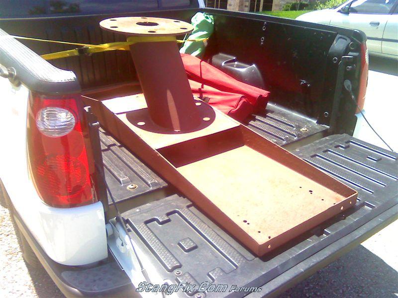
I also picked this up today, from the "free" section of my local CraigsList.

26_15_07_10_12_55_47.jpg


It's a huge arse diving board platform. That's all 1/4" steel. With a 1/2" base plate. So I virtually have an endless supply of steel to play with to form brackets.

Free! :vic
 
Modifying a non-important post to show how the bracket was made and keep stuff in order.

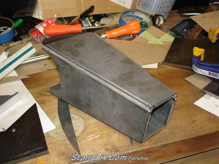
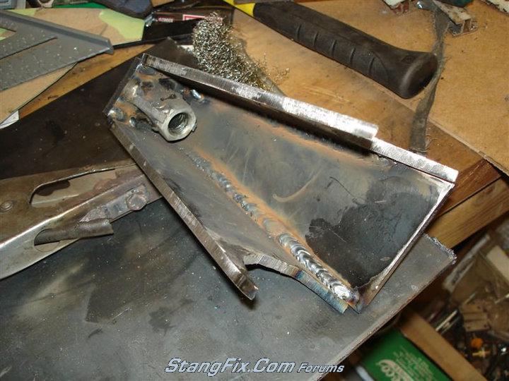
This is the Watts link rod mount which will become a combo shock mount as well.

It's all 1/4" steel.

I typically start with cardboard templates, etc for test fitting. I taped it all up and mounted it to the axle tube.
26_26_07_10_8_33_36_0.jpg


26_26_07_10_8_33_37_1.jpg


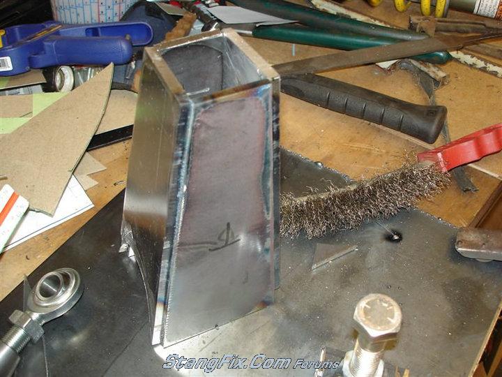
Forming the "box" (which is tapered)
26_26_07_10_8_33_37_2.jpg


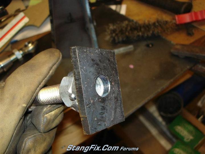
End plate which is internally nutted.
26_26_07_10_8_33_37_3.jpg


26_26_07_10_8_33_37_4.jpg


26_26_07_10_8_34_16_0.jpg


Gussted nut
26_26_07_10_8_34_16_1.jpg


Box with shock mount batwings
26_26_07_10_8_34_16_2.jpg


26_26_07_10_8_34_16_3.jpg
 
Alright, time once again for the weekend update... :ecit

The truck now rolls on it's own free will!

I finished fab'ing the rest of the rear end brackets for the Watts & the 4-link.

This is what I devised for the Watts link arm mounts. A combo bracket to mount the shock AND watts too. I was kind of bad about not photo-documenting stuff this weekend too.

The extension bracket is a fully boxed, all 1/4" plate welded internally and externally. There are 2 nuts welded together on the inside and gusseted as well for the bolt to thread into.

26_26_07_10_6_47_53_0.JPG


Welded to the axle tubes:
26_26_07_10_6_47_54_1.JPG


26_26_07_10_6_47_54_2.JPG


26_26_07_10_6_47_54_3.JPG


26_26_07_10_6_47_54_4.JPG


And jump ahead to the 99% finished product. I need to finish welding up the 4-link bar ends and get some shorter bolts - but that's about it.

26_26_07_10_6_48_27_0.JPG


26_26_07_10_6_48_27_1.JPG


26_26_07_10_6_48_27_2.JPG


Lower shock mount view:
26_26_07_10_6_48_27_3.JPG


26_26_07_10_6_48_27_4.JPG


The picture doesn't show it - but there is clearance there:
26_26_07_10_6_48_55_0.JPG


26_26_07_10_6_48_55_1.JPG


26_26_07_10_6_48_55_2.JPG


26_26_07_10_6_48_55_3.JPG


26_26_07_10_6_48_55_4.JPG


26_26_07_10_6_58_11_0.JPG
 
Last edited by a moderator:
Great looking work. I do believe you have crossed over from the "Rat Rod" to the "Custom" class of vehicle.
 
Jeremy,

What steps did you take to avoid overheating the axle tubes when welding on the brackets? I've been told by lots of people that they can warp fairly easily when doing such welding. Chassis guys I talked to use jigs with shafts running through the tubes to keep things straight and true. Am I worried about nothing here? This is the sole reason (other than my far less superior welding skill to yours) that I have decided to "farm" this job out.
 
Everything looks awesome, and your fabrication skills are in a different league.

What equipment do you use to cut all the steel plate pieces?
 
"Horseplay" said:
Jeremy,

What steps did you take to avoid overheating the axle tubes when welding on the brackets? I've been told by lots of people that they can warp fairly easily when doing such welding. Chassis guys I talked to use jigs with shafts running through the tubes to keep things straight and true. Am I worried about nothing here? This is the sole reason (other than my far less superior welding skill to yours) that I have decided to "farm" this job out.

No, no over-consciencely actions were taken, other than welding a portion (say, one edge) then bouncing over to the other bracket on the opposite side, etc & repeat.

Oh, does the fact that I ran out of wire and gas right in the middle of welding and having to run out and buy new wire and gas, count also? That was plenty of cool down time.

But honestly, this is not the first time that I have welded brackets to an axle tube - and I have never noticed problems in the past. But that doesn't mean much either... I guess if my seals start leaking on the ends I'll know.
 
"garner67" said:
Everything looks awesome, and your fabrication skills are in a different league.

What equipment do you use to cut all the steel plate pieces?

Believe it or not - but I just use my drop arm band saw. I just leave the arm in the upright position and walk the plate through the blade. That's why I can't do REAL tight, internal, curves - it binds the blade too badly. But I can still knock out some fairly tight curves though.
 
Lookin' great Jeremy. Your welds appear to be "master" quality and I'm impressed.


Two things....

1. Where's the "hump" for your 9" rearend? It looks more like an 8" than a 9".... or is it a Chevy rearend? I forget.

2. I believe that the coil diameter of those coils is too great for the weight of the rear of your car truck rat rod and that it's going to create an awfully "stiff" ride.
 
"daveSanborn" said:
Lookin' great Jeremy. Your welds appear to be "master" quality and I'm impressed.

Thanks.


"daveSanborn" said:
1. Where's the "hump" for your 9" rearend? It looks more like an 8" than a 9".... or is it a Chevy rearend? I forget.

I was told it was an early 9" rearend. It has the 5x5-1/2 big Ford bolt pattern. I, at one time, posted some detail shots of the rearend. If you are curious - or can identify better, look in my Gallery.

Actually just scroll up like 15 pages or so.


"daveSanborn" said:
2. I believe that the coil diameter of those coils is too great for the weight of the rear of your car truck rat rod and that it's going to create an awfully "stiff" ride.

I already agree 100%. I even reduced the pre-load on the coils too. That seemed to help a little bit though. I will back them off some more and check again.
 
If you can put a socket on the bottom 2 nuts, it's NOT a 9". Sure looks OK by your pics.
 
Hmmmm, looking at better pics of your rear axle, it does look just like this 8" on Kevinstang's site!
http://www.kevinstang.com/Ninecase.htm

rh3.jpg


"The little brother to the 9" housing is the 8" housing, note its more oval appearance when compared to the above two 9" housings.This one is out of a 65-66 Mustang, note the two dimples and fill plug."


Your pics:
26_12_07_10_10_45_13_0.JPG


Reading further.....

rh7.jpg


"One of the ways many people spot a 9" rear end in the car is by looking for the hump in the center of housing, this is not always the best way, as 9" housings made prior to sometime in 1966 do not have the this large center protrusion.The one shown above is out of a 63 Galaxie, note its roundish appearance, two dimples and fill plug in housing back. "
 
I will back them off some more and check again.


No, I don't think this will fix it. I'm not sure what the weight rating is for the coils, but looking at the diameter of the wire on the coils they appear to be in the 450-500# range. "Loosening them up" won't fix anything, they'll still be stiff as all get out. You probably need something along the lines of a 275-300# spring.

Something like this.... notice the thinner diameter of the coil's wire..... btw, this is TCP's rear coilover kit for a 69-70 Mustang that if memory serves me correctly uses a 275# coil spring.


5800-M10_AT.jpg


The coil springs you're using now would likely compress an inch..... if the rat rod fell off a cliff.

I only know this because the coil springs on my car are similar to what you're currently using. The rear end ride is "harsh" and the body absorbs WAY TOO MUCH. Replacing the coil springs is on my list of things to do.
 
It sure looks like that early 9" that you showed. And that's why the guy who sold it to me told me it was - a real early 9".
 
Back
Top