• Hello there guest and Welcome to The #1 Classic Mustang forum!
    To gain full access you must Register. Registration is free and it takes only a few moments to complete.
    Already a member? Login here then!

The T56 conversion into a 70 Mach 1

Thanks! I'm super pumped. :) The actual install the trans wasn't a huge issue, its the little stuff that comes with it that have been so time consuming, like pulling the dash and pedal support, relocating E-brake, etc.


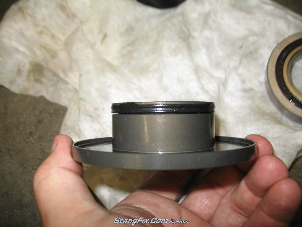
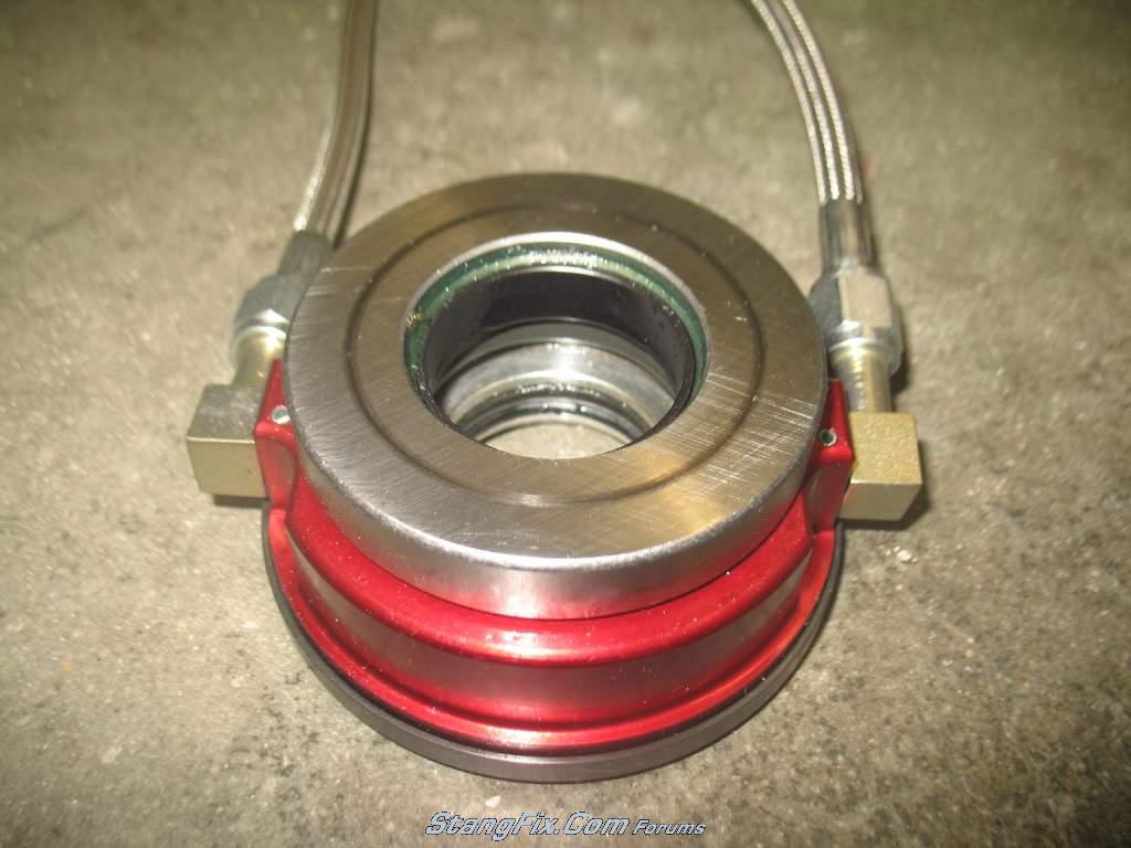
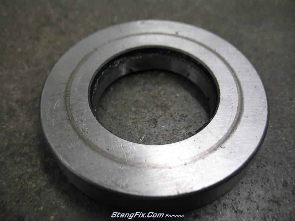
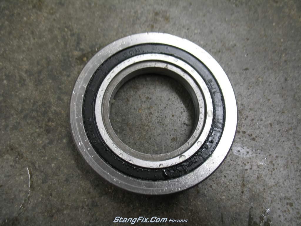
I need to check my hydraulic throwout bearing to make sure it is moving the correct distance. Bruce at Moderndriveline said that the bearing should travel 0.500". How in the world can I get a fairly accurate measurement? I can't get my caliper up in there. I guess I may have to use a tape measure or a busted ruler while my wife presses on the clutch pedal. Should I be worried about the exact travel, or should I just start the car and press in the clutch pedal and make sure the tires aren't spinning??
 
"buckeyedemon" said:
fwiw, this is straight from the 69 chassis assembly manual.

a 69 mustang 351W manual or auto

engine angle: 4*7' down
driveshaft angle: 2*29' down
pinion angle: 1*17' down

resulting engine/driveshaft u-joint angle: 1*33'
resulting pinion/driveshaft u-joint angle:3*46'

i'm curious to know what you have. i did a transmission swap but mine is only a shell and couldn't get a driveshaft angle measurement. all i know is that increased the engine angle on the order of 0.25 to 0.50 degrees as measured directly before and after the swap (351W, drop mounts, TKO, notched floor support, slight cut to the transmission tunnel and my own transmission mount).

it's very rare that anyone will publish these values.

Buckeye, I finally got to measure my angles. This is with the car still on the jack stands and the rear axle loaded under its own weight (front suspension not loaded). The engine angle is 3° down, the driveshaft angle is 2.5° down, and the pinion is 0°. The pinion and engine angle use the same part of the angle measuring device to avoid discrepancies. The engine angle was taken with the angle gauge facing the passenger side, while the angle gauge was facing the drivers side while measuring the pinion angle. I'm not sure how accurate these angle gauges are, but its all relative anyways.
 
hey thanks! i'm hoping my u-joint angle on the engine works out as good as that!. i had to do a little cutting to the tunnel brace and it still added 0.25 degree to my engine angle with a TKO.
 
I'd like to point out that these angle gauges are NOT very accurate. I have two of them and was curious what I'd get if I used my other gauge, as well as check angles from the other side (gauge facing drivers side when measuring trans). Needless to say they varied up to 2° in overall measurements, but the angle differential between the pinion and trans for all of them ended up being 3°. Soooo, I'm not 100% sure that my engine is 3° down but I do know that there is a 3° angle differential. Just an FYI, don't hold these angle gauges as super accurate....either that or its just my two that suck
 
it's the difference that matters. in addition it's hard to read those generic angle finders to within a half degree.

the paper insert with all the degree labels was originally shifted in mine, which was screwing with my head for awhile. i put the angle finder on a level, then rotated the paper to zero.
 
Totally agree Buckeye!!

To-do list has been updated. I am planning on starting the car once I get the alternator wire ran. I finished the parking brake solution that I had in my head, and it worked out wonderfully. Looking back now, I should have came up with this idea before painting my transmission crossmember. I started out with the stock parking brake bracket that I took off the car in order to install the trans crossmember (sorry for the fuzzy pics on some)

231_18_07_10_6_32_09_0.JPG


I then modified it by cutting it down and test fitting it in place. Since I cut it down so much, I was afraid the bracket would bend so I added a gusset. The only steel I had was 1/4", so I started with a 1/4" piece for a gusset and then filled in the left side with weld. Welding skills still aren't up to par yet but I'm getting my practice in with my die grinder :sad

Here is the gusseted bracket. I didn't bring the gusset all the way up to the top since the point of force will be at the center of the hole. I could have went up a little higher, but its not gonna move regardless.

231_18_07_10_6_32_09_1.JPG


Here is the backside

231_18_07_10_6_32_09_2.JPG


And here is the bracket welded to my transmission crossmember

231_18_07_10_6_32_09_3.JPG


231_18_07_10_6_32_10_4.JPG


Once that was installed, I needed to figure out the passenger side idler hook. The stock bracket was still welded to the floor pan and didn't really wanna remove it. I figured I could just mimic the hole in the stock bracket directly in my trans cross member. Two 1/2" holes spaced 1/2" apart and used a die grinder to cut the bump out.

231_18_07_10_6_33_19_1.JPG


231_18_07_10_6_33_19_0.JPG


This setup moves the location of the cables closer to the ground, so they now don't rub as bad on my floorpans as the did originally. The passenger exhaust clears the cable perfectly but the drivers side has the cable resting on the top of the pipe. I'm not sure what to do about that or if it really hurts anything. I may have to keep an eye on the cable to see if it frays or the heat affects it.

231_18_07_10_6_33_19_2.JPG
 
Last edited by a moderator:
It's ALIVE!!! :ecit :ecit I fired it up this evening and took it around the block. I only got it into 3rd gear at low RPMs cause its a neighborhood and my rear 3.00 gears keep the rpms low. I haven't renewed my plates in a few years, so I didn't want to risk getting a ticket taking it too far from the house. There were a few issues upon returning back to the driveway. I had a pretty steady oil leak, which I am pretty sure is coming from the oil pressure sending unit extension. I traced it directly where the brass pipe threads into the block. I'm gonna have to pull the fuel pump just to get to that bugger. I also temporarily ran wiring for a fan relay to run the Taurus fan on low speed until my DCControl box gets here. Well I didn't get it tied off good enough apparantly because the wires going through the old speedometer cable grommet got wrapped around the steering rag joint and tore it all to crap. Thankfully I was smart enough to use fuses. I got the wiring all taken care of this evening but plan on fixing the oil leak tomorrow.

As far as the ride, I'm already loving the manual trans. The clutch disengages too close to the floor for my taste. ModernDriveline claims that it should disengage 1.5" from the floorboard. When the pedal travels 7", I would expect it to disengage close to midtravel....not near the bottom. They claim that is how it was designed. Anyone else experience this with a non-ModernDriveline hydraulic clutch setup??
 
:pbj :10 Congrats on the maiden voyage!!!! If there is one thing I have learned in building my car is that rarely will things work like they are supposed to the first time. It seems like most things need a little tweaking to operate to my satisfaction.

My clutch is a JMC unit and it disengages about 40% up from the floor.
 
Well, gotta hold off on the celebration. I got the new plates today, installed them, and went to fill up the gas at the station a few miles away. Got it filled up and decided to take it down a highway to stretch its legs out. Everything worked like a charm, and when I got back into town I hit the last red light. I had taken many lights from a stop, as well as stop signs and didn't have any problems today (yesterday I killed it the first few times till I got the hang of it). This last light the car bucked and stalled. Started it up and went to put it into gear and it wouldn't go. The clutch pedal felt wayyy too soft, meaning it isn't disengaging/engaging the clutch. So I jump out the car and check the fluid reservoir and its full (my initial thought was it's leaking and ran out of fluid). There is enough resistance to hold the clutch pedal up, so I'm pretty sure the pedal linkage is fine, otherwise it'd fall to the floor and stay there. I'll double check it regardless. So that basically leaves the M/C or the hydro bearing that crapped out. :fbomb :fbomb :fbomb :fbomb
 
Well I went back to the car and towed it home. A quick peak under the car showed a small puddle underneath the bellhousing. :cry :cry

I won't have time to crawl under it till this weekend, but my guess is either the seals on the throwout bearing puked or if I get really lucky maybe the bleeder valve worked loose. My luck doesn't work like that typically.
 
Umm, yeah thats the downfall using the internal hydro bearing. It was eating at me so I left work early and crawled under the car. Indeed the hydro bearing is leaking fluid, but it appeared that the pressure plate didn't have any fluid on it. I wonder if the fingers on the pressure plate don't act like a fan and blows the fluid away. Regardless, its leaking fluid from the front and backside of the bearing. I sent ModernDriveline an email to see what all I can troubleshoot (if anything) before I drop the trans. I'm starting to become a pro at R&R this trans :rp
 
You're discovering firsthand the pleasures of a hydraulic throwout bearing.... more power to you!

I've changed/screwed with the hyd. throwout bearing on my Jeep Wrangler hopefully for the very last time. A few years back I R&R'ed the transmission, transfer case and both driveshafts... four times in one weekend. Lots of fun! Not.

It's probably something simple, but just getting to it to expedite a repair is the hard part.
 
Yeah I've heard a few people have had problems with them, but I mostly read praises. That is the downfall with hydraulic throwouts in that you have to drop the trans to service them. I knew that before buying it, I just thought it'd last longer than 5 miles :sad I'll be talking with Bruce at Moderndriveline today to see what he has to say about it.
 
Hydro bearing pulled today and was directed by ModernDriveline to disassemble the bearing to look for damaged seals. I did find one seal that was damaged in two spots.

231_24_07_10_2_45_29.JPG


231_24_07_10_2_46_01.JPG
 
Last edited by a moderator:
Interesting... I guess I'll disassemble mine before the final install and make sure those seals are good! Thanks for the update.
 
Mine worked fine at first, so the seals were good out of the box. It built pressure fine and had the proper bearing throw. I'm not sure if something inside got kinked or what the crap happened. All other seals looked great. If you are using a McLeod, be sure to read the directions carefully and make sure you use NON-Synthetic DOT3 only brake fluid. Apparently synthetic fluid is not compatible with the seals. I had to look everywhere for the non-synthetic stuff.
 
That's a bummer! At least you have a taste of what it's like to give you some motivation to get the final few issues resolved.

Did you check bellhousing alignment when you installed the bell? I wonder if it being off a few thousands would affect the seals under pressure if the TOB isn't exactly square to the clutch...
 
"65fast" said:
That's a bummer! At least you have a taste of what it's like to give you some motivation to get the final few issues resolved.

Did you check bellhousing alignment when you installed the bell? I wonder if it being off a few thousands would affect the seals under pressure if the TOB isn't exactly square to the clutch...

Yep, see Reply #43 for bellhousing alignment. I'd have preferred the final issues to not involve the bearing though :lol

McLeod noticed a green grease on the bearing pictures and asked if I added grease, which would contaminate the brake fluid in the piston. The green grease is actually leaking from the bearing piece as far as I can tell. Below are pictures illustrating this grease. I'm still waiting on the final word from ModernDriveline, who is working with McLeod on this issue. Bruce has been great to work with, and isn't pleased with this immediate failure on a newly redesigned throwout bearing.

Note the green grease at the interface of the inner bearing race and the black piston
231_27_07_10_8_05_08_0.JPG


Front of the bearing with grease visible
231_27_07_10_8_05_12_4.JPG


Backside of the bearing. Note the beading up of brake fluid near the joint of the inner race and the black seal
231_27_07_10_8_05_10_3.JPG


Green grease line on piston from leaking bearing
231_27_07_10_8_05_09_2.JPG


another pic of the piston with the grease
231_27_07_10_8_05_08_1.JPG


Basically, from my armchair analysis the bearing leaked the grease which then got into the piston cylinder. That contaminated the brake fluid and caused the cylinder walls to have remnants of grease, which likely increased friction on the cylinder walls and caused the seal to blow. Thats my theory anyways :sad
 
Last edited by a moderator:
Interesting! Keep this up to date as I will be pulling my trans again soon after final mock up. Would like to eliminate all possible problems before final assembly.
 
Back
Top