• Hello there guest and Welcome to The #1 Classic Mustang forum!
    To gain full access you must Register. Registration is free and it takes only a few moments to complete.
    Already a member? Login here then!

1952 F1: The Garage Roommate

Select from the following six options, derived from two basic designs w/ colors and options.

  • A

    Votes: 1 7.7%
  • B

    Votes: 7 53.8%
  • C

    Votes: 2 15.4%
  • D

    Votes: 0 0.0%
  • E

    Votes: 3 23.1%
  • F

    Votes: 0 0.0%

  • Total voters
    13
  • Poll closed .
Can you put the EPAS in the engine side of the firewall? Yeah, you'll be able to see it there, but just a thought out of the box.
 
So I'm out in the garage just adding to the list of independent little projects for the truck. I've got the underhood portion of the steering linkage all figured out and the parts in hand. Same for the inside the cab side including an Ididit style SS tilt column, a electric set-up out of an Equinox and some bits to connect the odd shafts of the GM unit to the wheel shaft and down to the front.

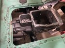
So here's the rub. I DO NOT WANT TO SEE the electric assist stuff. Just about every install I've seen has some or all of the drive hanging off the column in pretty plain sight. I get a little is likely necessary but I want to avoid it as much as I can. Here's what a stock column looks like. Just imagine wrapping an electric motor and gear box around that with it out in the open. Yuck.

View attachment 33766

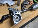
So I needed a solution. A little thought and then internet search later and I have a plan. There is an aftermarket part rodders have been using in the tight confines of early hot rods that off sets the input and output heights of steering shafts which would do just what I want. Issue is they want like $650 for one! I've got everything I need to build my own on order now for about $200 and that was with some excess aluminum stock and a big chuck of UHMW that I will have left over for other projects. Here's the part I'm writing about.

View attachment 33767

Going this route will let me tuck the electric unit way up under the dash as I can run the column up against the dash lip, closer to horizontal to the floor, using the tilt function to give me the angle needed at the wheel. Then the offset piece can drop the out put shaft height low on the firewall to keep it out of your face underhood and in a good position to connect to the rack. I've always intended to make a lower dash extension to curve it back under like the top (if you look at that first interior pic above, this lower piece will come down about as far as that underdash gauge) which would have the hole through which the column would disappear.

Sorry, for being so long winded (what's new). Just wanted to lay out the plan while fresh in my mind. Thoughts?
Could you do a false floor? Like box it to hide the drive? If you run a "box" right across driver to passenger side it might not stand out once covered with carpet. If you had to, you could extend the box on the engine bay side for depth. Easy to put an access plate on there for maintenance. If if looks ok you could hide other things in there.

Just a thought
 
Last edited:
Can you put the EPAS in the engine side of the firewall? Yeah, you'll be able to see it there, but just a thought out of the box.
Good thought. There is room but it would be right smack in your face. Pretty tight against the rear exhaust port as well, for my comfort. I thought about trying to hide it behind new bay panel structure but decided it would make things to "cramped" looking.
 
Could you do a false floor? Like box it to hide the drive? If you run a "box" right across driver to passenger side it might not stand out once covered with carpet. If you had to, you could extend the box on the engine bay side for depth. Easy to put an access plate on there for maintenance. If if looks ok you could hide other things in there.

Just a thought
Not really possible to change the floor layout. The pedal linkage and masters are hidden there now. Plus, the truck is equipped with air ride to drop it pretty low. Now putting the frame on the ground but low enough this set-up would not fit.
 
So I just wrote up a very long and detailed post of all I have been doing with the truck lately. Lots of particulars on what I did, why I did it and what I used, etc. And then I somehow hit something and it all went away. :mad:

I have stuff to do but still wanted to share so I will but in brief. I'm sure {.} will appreciate that I'm editing myself. So what got done? Primarily the steering column was modified to fit as needed and the electric assist assembly was mounted.
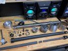
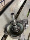
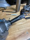
As the input shaft required cutting and a fabricated connector welded to the end, I had to dissemble the whole unit and remove the gearmotor section containing the input shaft from the unit entirely. There are torque sensors built into the thing that would get damaged or destroyed entirely with the current that welding would pass through them. So apart it all came followed by a visit to the band saw. I had previously taken the E-Bay purchased, Chinese manufactured steering column completely apart so I was able to cut a section of the female D tube shaft off to use in fabrication of the connector I needed. I welded it to a piece of hollow shaft that I drilled out to fit tightly over the unit's input shaft stub. That was the only actual modification of the GM assist unit I had to make, other than cutting the sensor wires to allow me to mount the once integral electronics box in another location under the dash. I will come back later when I wire the truck to make the extension harness.
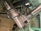
column disassembled.jpg
gear motor shaft cut.jpg
column coupler.jpg
mocked assembled column.jpg
Next up was designing and fabricating a mount for the column/motor. A lot went into this part. I wanted to get the motor up as high as possible as I hate seeing it hanging down low on so many installations I have seen. The challenges here are many but the primary one being that the end result needs to have the face angle of the steering wheel correct. I measured it on lots of cars and it seems about 70 degrees in relation to the ground is about where you want it. Having a tilt function gives me some room but I wanted it there in neutral so I could adjust as I see fit later.

I won't spend as much time this go around with how I built the upper support as you can see it in the pics. I welded a bit to the firewall with studs it slides onto and it rest un the lower lip of the dash and is held in place with bolts. Very solid. The key bit in mounting was a triangular shaped piece that fits snugly around the gearbox bearing race casting. this and the secondary bracket that ties into the factory mounting point suffice to not only hold the unit in place (in the position that has the shallowest of extension from shaft center to help hide it) but also resist the rotational torque forces of it in operation. This unit can crank out up to 700# of torque so the mounting needs to be SOLID.
column mounted 1.jpg

Once the mount was done next up was cutting the column to length. Sounds easy but it certainly was not. There is an inner "D" shaft that connect the wheel to the assist unit. It slips into that coupling I made and welded to the unit. There is an inner tube that runs inside the outer column tube to protect the wiring but also is integral to the mounting of the lower column cone as well as the lower-half of the tilt mechanism. All of these have different length requirements, some being different alterations from stock due to how I modified other components. Check your math, measure twice before cutting!

One of those bits that changed things up was the part I had to make to connect the outer column tube to the actual assist unit. That lower mount has a face just like the bracket I made for the motor unit. A triangular, three bolt arrangement. To it I welded up some modified pieces of a couple exhaust pipe reducers so that each end fit snuggly around their mating partners. In the end, it looks very clean and does a great job so keeping everything secure and true.
 
Well done Terry. Its not so easy that thing called steering column and EPAS making it work together.
 
I think you don’t understand the definition of “editing”


Mark
You have no idea how much I cut from the first effort. Plenty of pics of the various parts being fabricated. Some basic but very useful tips on how to do things to, for example, make sure holes/studs will align perfectly when assembled. Some long winded explanation of how and why I built the upper support the way I did (hint: EPAS gear motors produce a lot of torque).

I had originally intended to do a long tutorial kind of post on incorporating such a unit into any steering column but, honestly, it just takes too damn long. Having to stop and remember to take pictures every few minutes didn't work out so well. Not too mention, as I found, each application can throw new wrinkles at you. For example, the unit I used has metric dimensional components and very unique spline counts as well. If you have access to a lathe not a big deal but otherwise you have to get creative.

Remember as well, my main goal aside from gaining steering assist was to be able to stuff that thing up and out of sight as much as possible. That meant changing shaft angles, etc. If you look at the one pic I posted of the unit installed you'll see a universal joint hanging off the back. from there I can either run a simple shaft down/out the firewall and then couple it as needed to meet up with the rack input or do as originally planned and run it horizontally via another shaft to connect to the offset I will build to drop it down to exit out at floor level. the way things look so far it is 50/50 if I will go the latter route. I may not need to to accomplish my intentions. To be decided later. I will still build the offset unit though as I already bought all the bits and want to give it go!
 
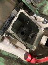
So next decision/complication involves the transmission mount. In the pics below, you'll see how there is not clearance for the T5 case to pass over/through the current original crossmember. I went ahead and notched and modified it to make room.
trans fit 3.jpg
trans fit 1.jpg
trans fit 2.jpg
Having done that I was able to bolt on the tailshaft housing to verify clearance for it as well. You'll see it was thisclose to fitting with just the last little bit hitting the floor pan. All of this is set-up with the chassis at level ride height and the engine sitting level. I will likely have to add a couple degrees of rake to the engine position to gain a bit more clearance underneath for the driveshaft. I cannot lower the engine anymore.
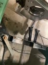
crossmenber modification.jpg
trans mockup.jpg
So here's the issue. If I leave the current crossmember and everything else as is the only way to service the trans or replace a clutch disc will be to pull the engine. The current crossmember is the mounting point for both the factory brake and clutch pedals as well as the underfloor master cylinder. I am keeping all of this in place. an alternative solution would be to make a new crossmember and locate it further back in the chassis but the location of the brake master cylinder would be right in the way. I can't see a good way around that issue.

I see two ways to go.

1. Cut the center section of the modified crossmember out and modify it all to make it bolt in. I'd also need to extend the factory floor cut-out just a bit to give the transmission room.

2. Extend the floor cut-out back to give the transmission room to move and the input shaft to clear the bellhousing but leave the crossmember complete. This would mean the trans/clutch servicing would happen from above. Pull it out the top!

I'm leaning hard to option 2. Why? The floor has to be opened up either way and this path leaves the crossmember in its most structurally sound condition. As the actual trans mount has to connect to the crossmember and be cantilevered out some 6" or so to the actual mounting point on the trans tailshaft housing, I think it the best for strength. Most importantly, I wouldn't be crawling around under the truck with a T5 on my chest!

Thoughts? Alternative ideas?
 
Last edited:
I really think option 1 would be my preferred method. Pulling the engine is a non-starter, especially considering all that will be attached to it. I am also not a fan of having to access it from inside the cab. That would require the removal of nearly all of the interior just to swap out a clutch. Making a bolt-in, removable cross member that is as strong or stronger than the original should not be hard for a guy like you.....just look at all the engineering that went into just your steering column! While I agree removing a T-5 from below is not fun, it is doable at least twice. Ask me how I know! Plus you can get a somewhat cheap HF trans jack to make it a bit easier. Or buy a lift!
 
I am leaning to option 1 also. Its more work but you don't swap a clutch every year or so. And when you do , find someone who has a lift. My2cents.

Verstuurd vanaf mijn SM-T805 met Tapatalk
 
Everyone is always so fast to want to make more work for me. It's like having extra wives, I tell ya!
 
You will thank us the first time you have to pull that transmission! An investment in a lift would certainly make today's work easier and is much better in the long run! Just like a wife, we are good at spending your money.
 
View attachment 33851
So here's the issue. If I leave the current crossmember and everything else as is the only way to service the trans or replace a clutch disc will be to pull the engine. The current crossmember is the mounting point for both the factory brake and clutch pedals as well as the underfloor master cylinder. I am keeping all of this in place. an alternative solution would be to make a new crossmember and locate it further back in the chassis but the location of the brake master cylinder would be right in the way. I can't see a good way around that issue.

I see two ways to go.

1. Cut the center section of the modified crossmember out and modify it all to make it bolt in. I'd also need to extend the factory floor cut-out just a bit to give the transmission room.

2. Extend the floor cut-out back to give the transmission room to move and the input shaft to clear the bellhousing but leave the crossmember complete. This would mean the trans/clutch servicing would happen from above. Pull it out the top!

I'm leaning hard to option 2. Why? The floor has to be opened up either way and this path leaves the crossmember in its most structurally sound condition. As the actual trans mount has to connect to the crossmember and be cantilevered out some 6" or so to the actual mounting point on the trans tailshaft housing, I think it the best for strength. Most importantly, I wouldn't be crawling around under the truck with a T5 on my chest!

Thoughts? Alternative ideas?

I looked at the T5 upgrade for my '48 awhile back.
Leave only the driver's side of the factory crossmember in place..... needs to be there for the master cylinder/pedal support.
Remove the vast majority of right side of the factory crossmember.
Build a new crossmember that has the pickup point for new trans case. You should be able to fab one that fits that area.
This restores the framerail to framerail integrity. Tie in the new crossmember on the left side to the remaining portion
of the original crossmember. (I was going to build my new crossmember out of an original one and make the center section
removable so you could drop the transmission for servicing. That lifting the transmission procedure up through the interior is BS)
 
Back
Top